Publication 1763-RM001C-EN-P - October 2009
Function Files 69
Active Node Table Block of Communications Status File
If you are using RSLogix 500 version 7.00.00 or higher, you can view the
active node table by clicking on “Processor Status” and then selecting the
tab for the configured channel.
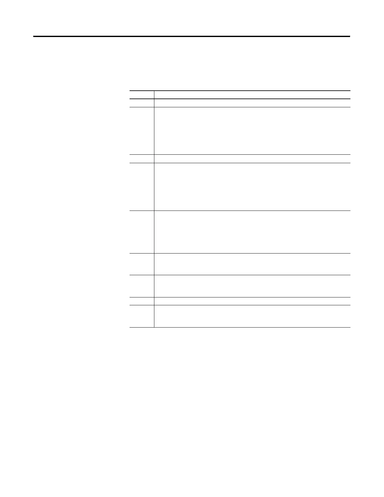
Active Node Table Block
Word Description
23 Active Node Table Category Identifier Code (always 3)
24 Length:
•always 4 for DH-485
•always 18 for DF1 Half-Duplex Master
•always 0 for DF1 Full-Duplex, DF1 Half-Duplex Slave, Modbus RTU Slave, Modbus
RTU Master, and ASCII
25 Format Code (always 0)
26 Number of Nodes:
•always 32 for DH-485
•always 255 for DF1 Half-Duplex Master
•always 0 for DF1 Full-Duplex, DF1 Half-Duplex Slave, Modbus RTU Slave, Modbus
RTU Master, and ASCII
27 Active Node Table (DH-485 and DF1 Half-Duplex Master) – Nodes 0 to 15
(CS0:27/1 is node 1, CS0:27/2 is node 2, etc.)
This is a bit-mapped register that displays the status of each node on the network. If a
bit is set (1), the corresponding node is active on the network. If a bit is clear (0), the
corresponding node is inactive.
28 Active Node Table (DH-485 and DF1 Half-Duplex Master) – Nodes 16 to 31
(CS0:28/1 is node 16, CS0:28/2 is node 17, etc.)
29 Active Node Table (DF1 Half-Duplex Master) – Nodes 32 to 47
(CS0:29/1 is node 32, CS0:29/2 is node 33, etc.)
…
42 Active Node Table (DF1 Half-Duplex Master) – Nodes 240 to 255
(CS0:42/1 is node 240, CS0:42/2 is node 241, etc.)
efesotomasyon.com - Allen Bradley,Rockwell,plc,servo,drive

 Loading...


