Publication 1763-RM001C-EN-P - October 2009
546 Knowledgebase Quick Starts
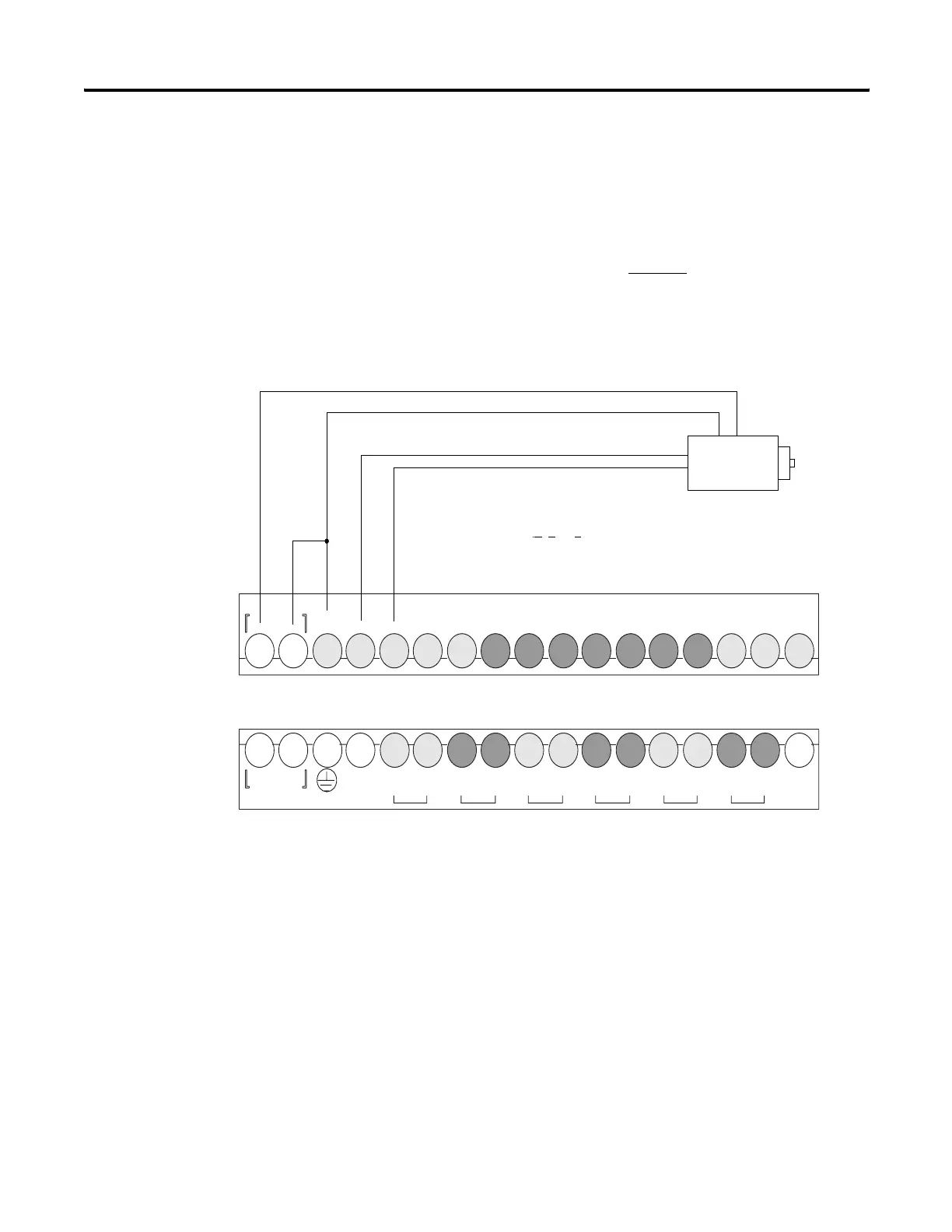
Proper wiring of a single ended encoder (Typical Allen-Bradley 845TK)
when configuring HSC.MOD for Mode 6 (Quadrature Counter)
The following diagram illustrates connecting an encoder to the
MicroLogix 1100.
The minimum configuration required for Mode 6
operation is to enter a
file number for the PFN parameter, set the AS and CE bits to a (1) and
enter a (6) for the MOD parameter.
TROUBLESHOOTING
Problem #1:The input display on the MicroLogix LCD screen turn on and
off, but no counts are seen in the HSC accumulator.
Solution:The input filter frequency may need to be adjusted in order to
capture the input pulses.
Follow the steps below.
DC
COM-
VAC O/0
VDC
VAC O/1
VDC
VAC O/2
VDC
VAC O/3
VDC
VAC O/4
VDC
VAC O/5
VDC
NOT
USED
NOT
USED
L1 L2/N
100-240 VAC
DC OUT
+ 24V
I/1I/0 I/2 I/3
DC
COM
I/4 I/5
IA
COM
IV1(+) IV2(+)I/6 I/7 I/8 I/9
Note: If the encoder is a High Voltage Differential Line Driver, do
not terminate A, B, or Z.
1763-16BWA
efesotomasyon.com - Allen Bradley,Rockwell,plc,servo,drive

 Loading...


