Publication 1763-RM001C-EN-P - October 2009
Knowledgebase Quick Starts 557
Minimum Hardware/Software requirements
• All MicroLogix 1100
• MicroLogix 1200 Series B FRN 2
• MicroLogix 1500 Series B FRN 4
• RSLOGIX 500 v7.00.00
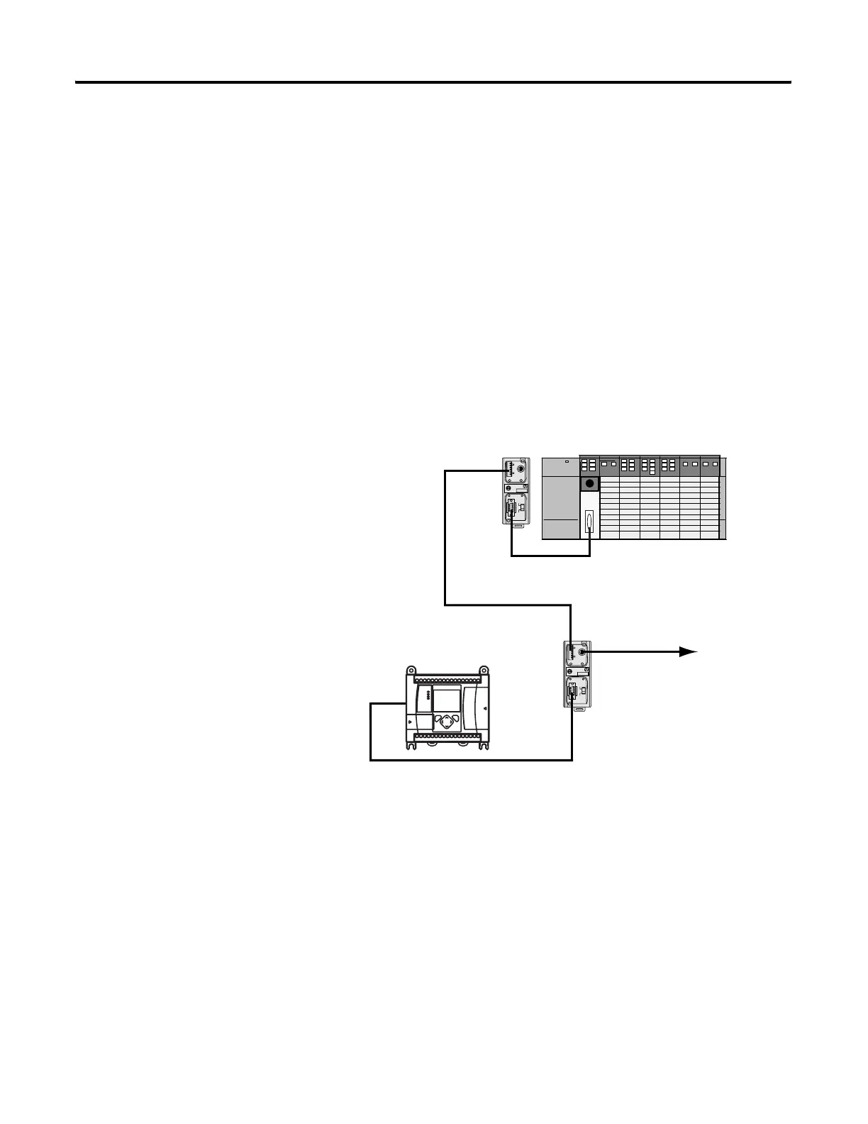
Example
The example shows network connections using DH-485, however DF1
Full or Half Duplex Ethernet/IP will also work.
1. Configure the SLC's Channel 0 port for DH-485 protocol.
2. Enter the following ladder logic into the SLC processor.
TERM
A
B
COM
SHLD
CHS GND
TX
TX PWR
TX
DC SOURCE
CABLE
EXTERNAL
TERM
A
B
COM
SHLD
CHS GND
TX
TX PWR
TX
DC SOURCE
CABLE
EXTERNAL
Additional MicroLogix 1200/1500s
+
v
c
1747-CP3
MicroLogix 1100
efesotomasyon.com - Allen Bradley,Rockwell,plc,servo,drive

 Loading...


