100 Rockwell Automation Publication 7000-UM202D-EN-P - May 2018
Chapter 2 Power Component Definition and Maintenance
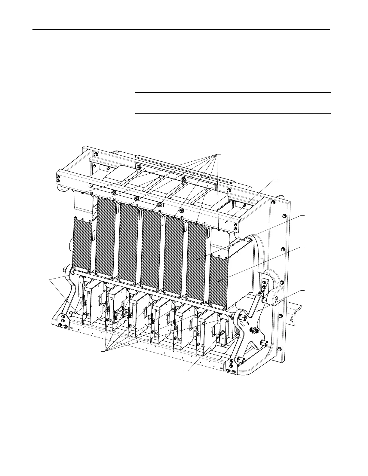
b. Tighten the clamp to the proper force until you can turn the
indicating washers by the fingers with some resistance.
17. Once clamp force has been re-applied, tighten heatpipe locking nuts on
top of horizontal fin support (center nut at each sink) to 8 N•m
(6 lb•ft).
Figure 87 - Heatpipe PowerCage Module
PowerCage Gasket
To ensure all air movement is through the slots of the heatsinks, all possible air
leaks are sealed with a rubber gasket between the surface of the PowerCage and
heatsink module. The gasket maintains proper cooling of the SGCTs or SCRs.
IMPORTANT Do not re-tighten nylon shipping bolts on 6600V drives. They are for shipping
purposes only.
Heatpipe locking nuts
Horizontal Fin Support
Clamp Head
Glass Rods
Clamp
Head
White Heatpipe
Retaining Bracket
Nylon Shipping Bolt
Heatpipe
End Position
Heatpipe

 Loading...


