Rockwell Automation Publication 7000-UM202D-EN-P - May 2018 85
Power Component Definition and Maintenance Chapter 2
SCR Anode-to-Cathode Resistance
Performing an anode-to-cathode resistance test verifies the integrity of the
SCR. The SCR uses the snubber circuit to power the self-powered gate driver
boards. The resistance measurement taken across each SCR should be
constant; an inconsistent value may indicate a damaged sharing resistor, self-
powered gate driver board or SCR.
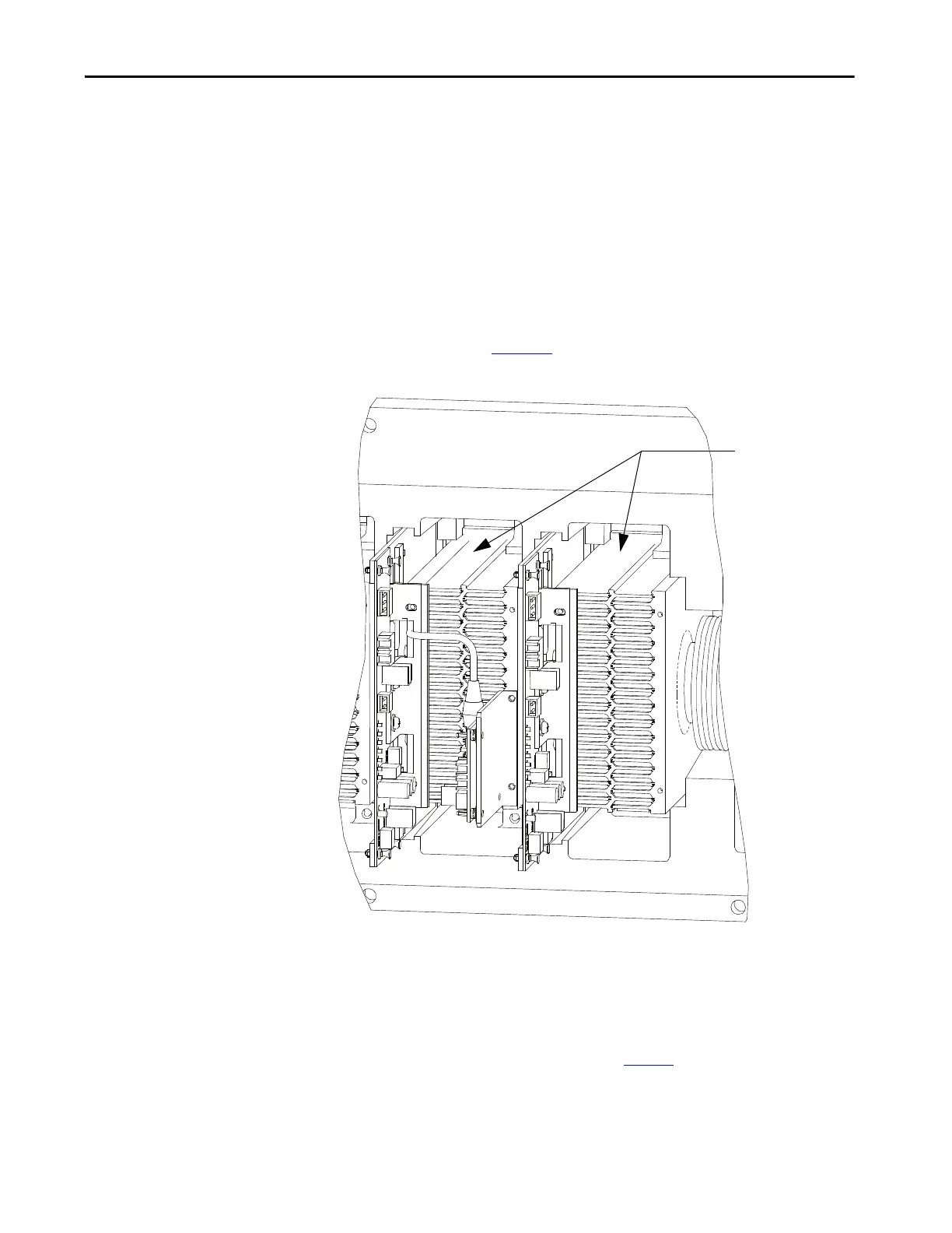
Using an ohmmeter, measure the anode-to-cathode resistance across each SCR
in the rectifier bridge, while looking for similar resistance values across each
device. Easy access from the anode-to-cathode is available by going from
heatsink-to-heatsink (Figure 75
).
Figure 75 - Anode-to-Cathode test
A good SCR and circuit should read between 22 and 24 k.
An SCR that has failed from anode-to-cathode will commonly produce a
resistance value of 0 for a shorted device or
∞Ω for an opened device. Unlike
the SGCT, it is highly irregular for an SCR to have a partially shorted device. If
an SCR is found to be out of tolerance, see page 90
for detailed instructions on
how to replace the SCR assembly.
Resistance value
between two
heatsinks is
Anode-to-Cathode
resistance

 Loading...


