150 Rockwell Automation Publication 7000-UM202D-EN-P - May 2018
Chapter 3 Control Component Definition and Maintenance
If the application is running, there are two other possible states for D9 and
D11, described below.
Replacing the Drive Processor Module
Before replacing the drive processor module, record all of the programmed
drive parameters and settings; specifically, the parameters, fault masks, fault
descriptions, and PLC links. This information resides in NVRAM on each
board, and as a result you may lose your settings with a new board. Save
parameters in the terminal memory. Other options include a flashcard,
HyperTerminal, the door-mounted printer, or DriveTools™ to record the
parameters to a file. The printer and HyperTerminal options enable you to
print configuration information. Otherwise, record information by hand. If a
board fails, you likely cannot save parameters after the failure.
Save all parameters after commissioning or servicing the drive. If you do not
have a copy of the initial configuration or current parameters, contact your
Rockwell sales or service representative or Product Support to check if they
have a copy.
1. Record all drive configuration using one of the options above.
2. Isolate and lock out all medium voltage and control voltage power to the
drive.
3. Remove the transparent sheet on top of the drive processor module by
removing the four screws.
4. Use a grounding static strap before removing any connectors.
5. Remove the connectors J4, J11 and J12 after proper identification and
marking if necessary. Use the electrical drawing as the reference.
6. Remove the four screws on the corners of the board fastening the board
to the standoffs on the analog control board.
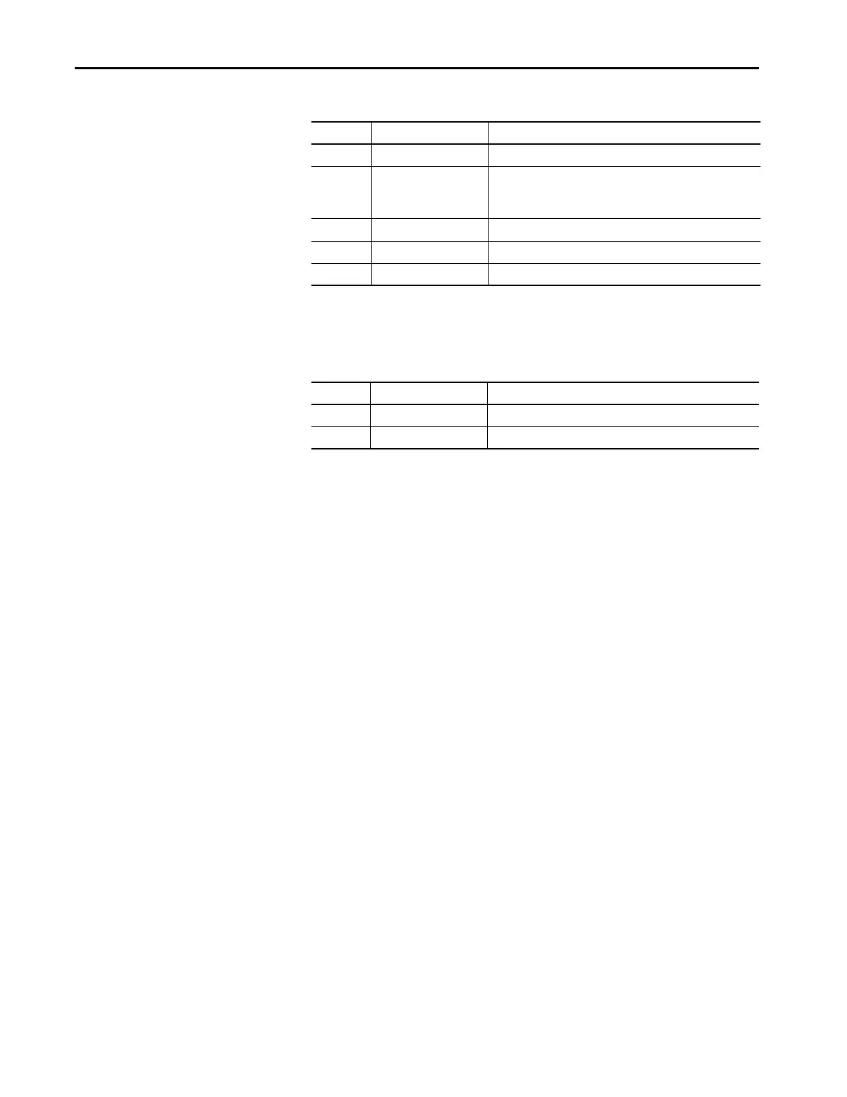
Red 8 count FPGA Loading failed
Red 9 count POST – USART failed:
1 Green Count = Port 1
2 Green Count = Port 2
Red 10 count End of code reached
Red 11 count Download – CRC error
Red 14 count Download – Overflow error
Table 8 - Alternate D9 and D11 Descriptions
LED State Meaning
D9 (Inv) Off Parameter load timeout
D11(Rect) Red FPGA real-time clock failed
Table 7 - Description of D9 and D11 Function: Boot Code Status (Continued)
Color Rate or Count (Pulse) Meaning

 Loading...


