Rockwell Automation Publication 7000-UM202D-EN-P - May 2018 149
Control Component Definition and Maintenance Chapter 3
Diagnostic test points on the DPM have a voltage output range of -5…+5V.
Table 5
identifies test points on the DPM.
This table defines the states of LEDs D9 and D11 on the DPM board, which
uses D9 for the inverter side processor, and D11 for the rectifier side processor.
The other two LEDs (D6 and D7) are the watchdogs for the inverter and
rectifier code respectively.
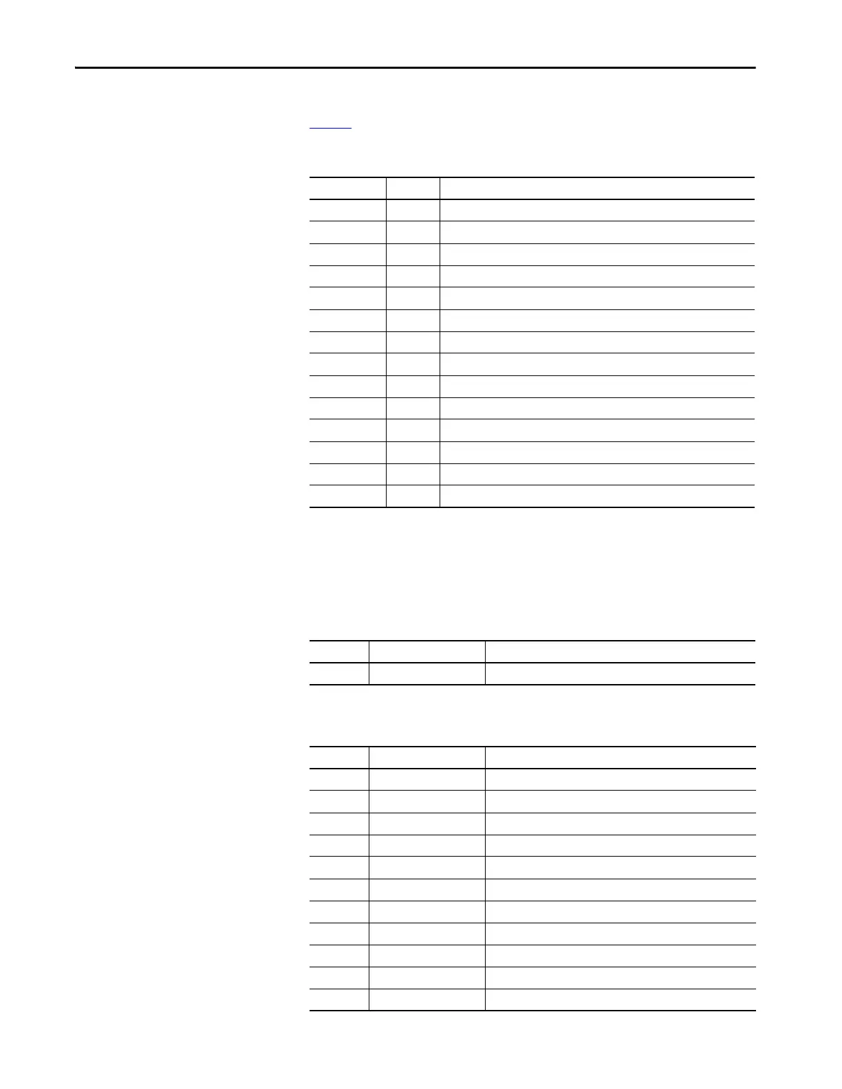
Table 5 - Test Points on Drive Processor Module
Test points Name Description
DPM-TP1 +1.2V +1.2V DC power supply
DPM-TP2 +1.8V +1.8V DC power supply
DPM-TP3 +2.5V +2.5V DC power supply
DPM-TP4 +3.3V +3.3V DC power supply
DPM-TP5 +5V +5V DC power supply
DPM-TP6 DGND Digital ground
DPM-TP7 ITP1 Digital to analog output – Assignable diagnostic test point
DPM-TP8 ITP2 Digital to analog output – Assignable diagnostic test point
DPM-TP9 ITP3 Digital to analog output – Assignable diagnostic test point
DPM-TP10 ITP4 Digital to analog output – Assignable diagnostic test point
DPM-TP11 RTP1 Digital to analog output – Assignable diagnostic test point
DPM-TP12 RTP2 Digital to analog output – Assignable diagnostic test point
DPM-TP13 RTP3 Digital to analog output – Assignable diagnostic test point
DPM-TP14 RTP4 Digital to analog output – Assignable diagnostic test point
Table 6 - Description of D6 and D7 Function
Color Rate or Count (Pulse) Meaning
Green Solid Application firmware is running
Table 7 - Description of D9 and D11 Function: Boot Code Status
Color Rate or Count (Pulse) Meaning
Green 10 count Pre-execution OK
Red .25 Hz No bootcode
Green .25 Hz No application
Green .5 Hz Downloading via serial port
Green 2 Hz Serial port active – terminal
Green 1 Hz Waiting/loading application
Green Solid Application running
Red Solid Operation failed
Red 2 count POST – RAM failed
Red 3 count POST – NVRAM failed
Red 4 count POST – DPRAM failed

 Loading...


