Rockwell Automation Publication 7000-UM202D-EN-P - May 2018 123
Power Component Definition and Maintenance Chapter 2
Fan Installation
Take care when handling the fan as poor handling can adversely affect its
balance.
Install the fan in the reverse order of its removal.
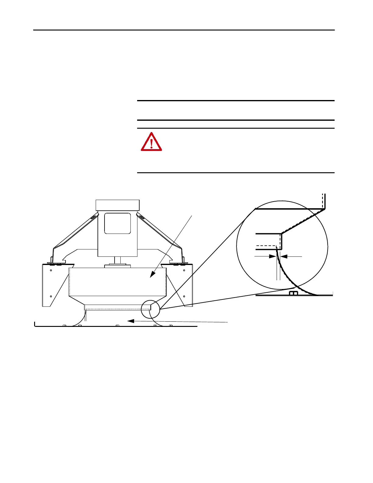
Figure 107 - Fan Assembly Installation
IMPORTANT After installation, rotate the impeller by hand to verify it is clear of the inlet
ring.
ATTENTION: The fan assembly must be radially centered. Use a feeler gauge
or similar tool to measure the gap between the impeller shroud and inlet
ring. The gap must be at least 6.3 mm (0.25 in.). To adjust the gap space,
loosen the hardware connecting the inlet ring to the cabinet plate and adjust
the inlet ring as necessary.
Outer Fan Shroud
Inlet Ring
Gap MUST
be 6.3 mm
(0.25 in.) on
both sides

 Loading...


