170 Rockwell Automation Publication 7000-UM202D-EN-P - May 2018
Chapter 3 Control Component Definition and Maintenance
Each OIB board also has input RX7 for a signal from a temperature feedback
board. The quantity and location of thermistor connections is dependent on
the drive configuration. Typically, there is one temperature sensor from the line
converter and one temperature sensor from the machine converter, each going
into the respective OIB board in the ‘A’ position. However, some drive
configurations only require one thermistor feedback connection. The
temperature feedback connection on OIBC is not implemented on the OIBB
and is never used. For more information, see the drawings supplied with your
drive. The alarm and trip set points for each of these signals are programmable
in software.
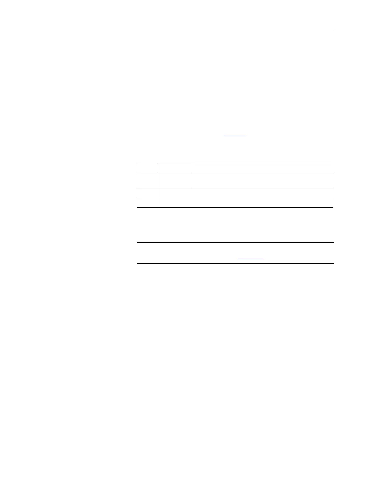
There are three LEDs on the OIB. Table 15
illustrates the status and
description for the LED states.
Replacing the Optical Interface Board
1. Isolate and lock out all power to the drive.
2. Mark the location and orientation of all the fiber optic cables. Use the
electrical drawing for reference.
3. Ground your static strap, and disconnect all of the connections. You may
need to remove the 60 core cable connectors on the Optical interface
base and the ground connection for access to the standoffs
4. Remove the OIB board from the OIBB. There are four standoffs that
snap into place on the OIB, and they need to be carefully handled when
disconnecting the boards. There is also the 28-pin connection between
the boards, and this connection should be handled carefully as you do
not want to bend the pins.
5. Install the new OIB on the OIBB. Ensure the standoffs snap into place.
6. Reconnect all fiber optic connections and verify the locations.
7. Apply low voltage power and complete gating, system, and medium
voltage tests to confirm board performance.
Table 15 - Color Explanation for OIB LEDs
LED Status Description
D1 Red – On Run – The OIB has received an enable signal. The drive control software is in control
of all gating.
D2 Yellow – On Ready – The OIB power supply is sufficient for proper operation.
D3 Green – On Power – The OIB has received a voltage signal greater than 2V.
IMPORTANT If the drive is equipped with the Safe Torque Off option, the drive will use
OIB2 boards. See publication 7000-UM203
to replace the OIB2 boards.

 Loading...


