Rockwell Automation Publication 7000-UM202D-EN-P - May 2018 161
Control Component Definition and Maintenance Chapter 3
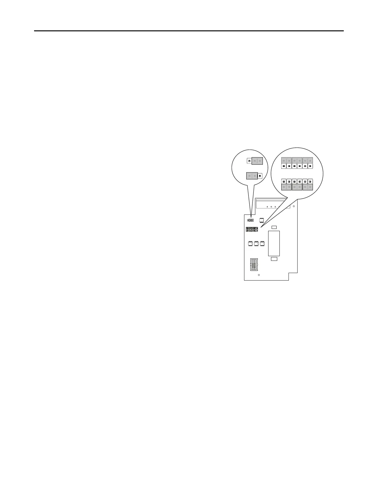
20B-ENC-3 Encoder Interface
This encoder interface enables connecting the drive to a standard quadrature
encoder. The 20B-ENC encoder interface provides three optically isolated
differential encoder inputs for A and B phases as well as a Z track. You cannot
configure these inputs for use with a single ended encoder. The board only
supports differential encoders. The board also provides a galvanically isolated
12V/3 W supply to power the attached encoder. You can configure the 20B-
ENC-3 encoder interface for 5V operation, however Rockwell Automation
recommends operation at 12V.
Figure 136 - 20B-ENC-3 Encoder Interface
Operation at 5V does not support long cable lengths, given the need to
regulate power within 5% at the encoder. Cable resistance and capacitance
makes it difficult to regulate power at the encoder to 4.75V. Longer cables may
decrease voltage below 4.75V, causing encoder malfunction. As a general rule,
using 18 Avg cabling with an Rdc of 19.3 Ω/km limits the cable length to 12 m
(42 ft) from the board to the encoder.
Input Connections
All encoder interface connections occur at J1, as follows.
J1 Pin 1 A+
J1 Pin 2 A-
J1 Pin 3 B+
J1 Pin 4 B-
J1 Pin 5 Z+
J1 Pin 6 Z-
J1 Pin 7 encoder power return
J1 Pin 8 encoder power (+12V @ 3 W)
J3
J3
J2
+12V
1
2
3
12 11
21
+5VR EF
1
2
3
+5V
+12V
1
2
3
+12V
+5V
12 11
21
12 11
21
J2
NOTE: Must be configured for
12V operation
Output
Config.
Input
Config.

 Loading...


