Rockwell Automation Publication 7000-UM202D-EN-P - May 2018 93
Power Component Definition and Maintenance Chapter 2
4. Torque the heatsink bolts to 13.5 N•m (10 lb•ft) starting with the
center heatsink and moving outward alternating left to right.
5. Check the clamp indicating washer.
Checking Clamping Pressure
Periodically inspect the clamping force in the PowerCage module. Ensure there
is no power to the equipment.
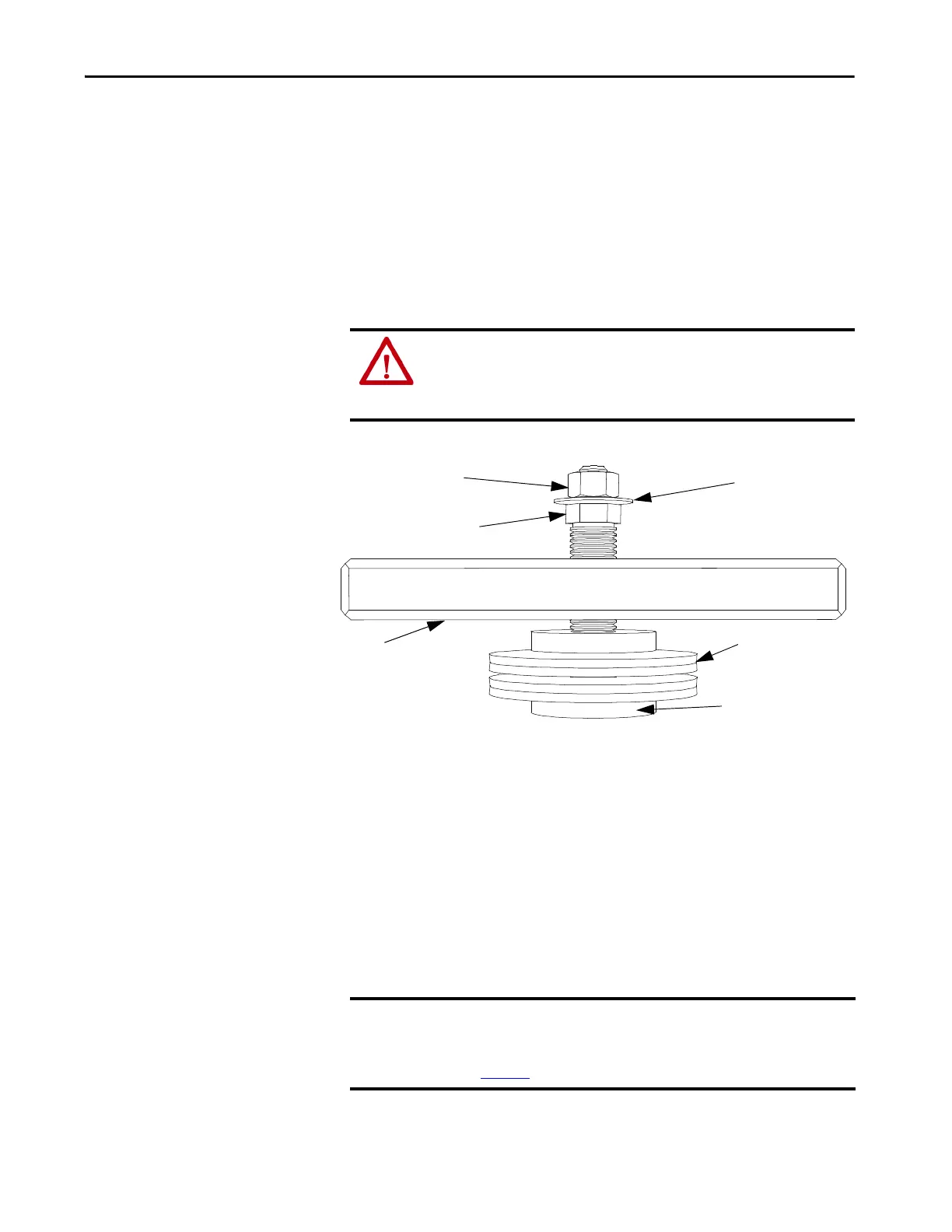
Figure 82 - Clamp Head Illustration
Clamping Pressure Adjustment
1. Disconnect all power to the drive.
2. Do not loosen the adjustment nut. If you loosen the clamping pressure,
carry out the assembly procedure to ensure uniform pressure on the
thyristors.
3. Tighten with a 21 mm wrench on the adjustment nut (upward motion)
until you can turn the indicating washer by fingers with some resistance.
The calibration nut should not spin freely.
ATTENTION: To prevent electrical shock, disconnect the main power before
working on the drive. Verify that all circuits are voltage-free using a hot stick
or appropriate voltage-measuring device. Failure to do so may result in injury
or death.
Calibration Nut - DO NOT ADJUST
Clamp Bar
Disc Springs
Pressure Pad Face
Indicating Washer
Adjustment Nut
IMPORTANT Do not adjust the calibration nut located outside the indicating washer at the
end of the threaded rod. The rotation of the calibration nut will affect the
torque calibration, which is factory-defined. Only adjust the adjustment nut
(see Figure 82
).

 Loading...


