158 Rockwell Automation Publication 7000-UM202D-EN-P - May 2018
Chapter 3 Control Component Definition and Maintenance
The recommended connection is shown above. The type of shielded cable used
is application specific and is determined by the length of the run, the
characteristic impedance and the frequency content of the signal.
Isolated Process Receiver
These inputs are individually configurable to accept either a -10/0/+10V input
signal or a 4-20 mA signal. When configured for voltage input, each channel
has an input impedance of 75 K Ω. When used as a current loop input, the
transmitter must have a minimum loop compliance of 2V to satisfy the 100 Ω
input impedance. Regardless of input configuration, each input is individually
isolated to ± 100V DC or 70V RMS AC.
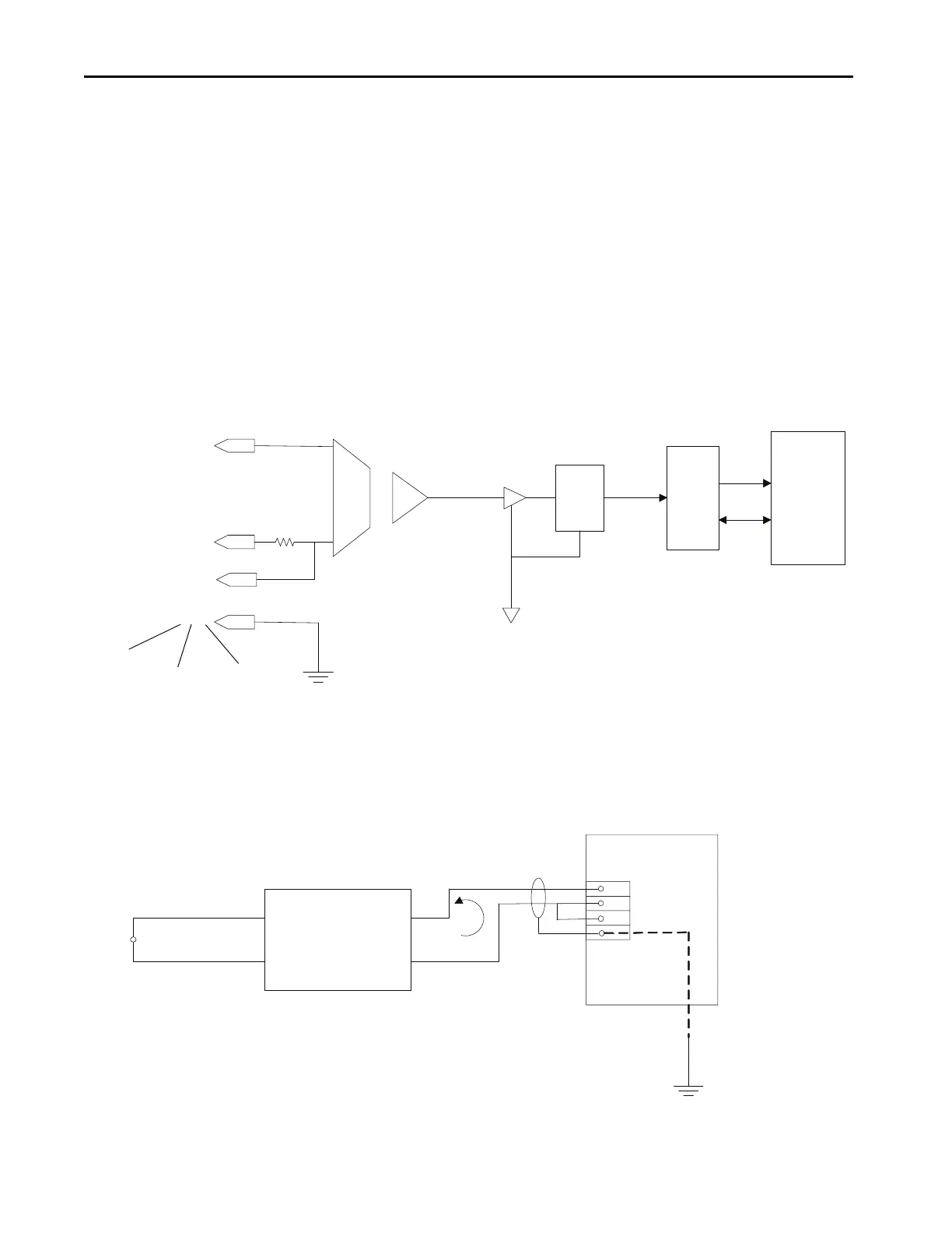
Figure 133 - Process Loop Receiver block diagram
The receiver can accept 4-wire transmitters. The figure below shows the
recommended connections. Again, the type of shielded cable used is
application specific as per the transmitter.
Figure 134 - Process Loop Receiver connections
+
Isolation Amplifier
FPGA
DSP
1, 5, 9
2, 6, 10
3, 7, 11
4, 8, 12
1st I/P Pins
2nd I/P Pins
3rd I/P Pins
VP
P
G
N
D
O
u
t
R
T
N
D
C
IFM
20
21
19
22
4-Wire Transmitter
User-supplied Power
(Sinking)

 Loading...


