164 Rockwell Automation Publication 7000-UM202D-EN-P - May 2018
Chapter 3 Control Component Definition and Maintenance
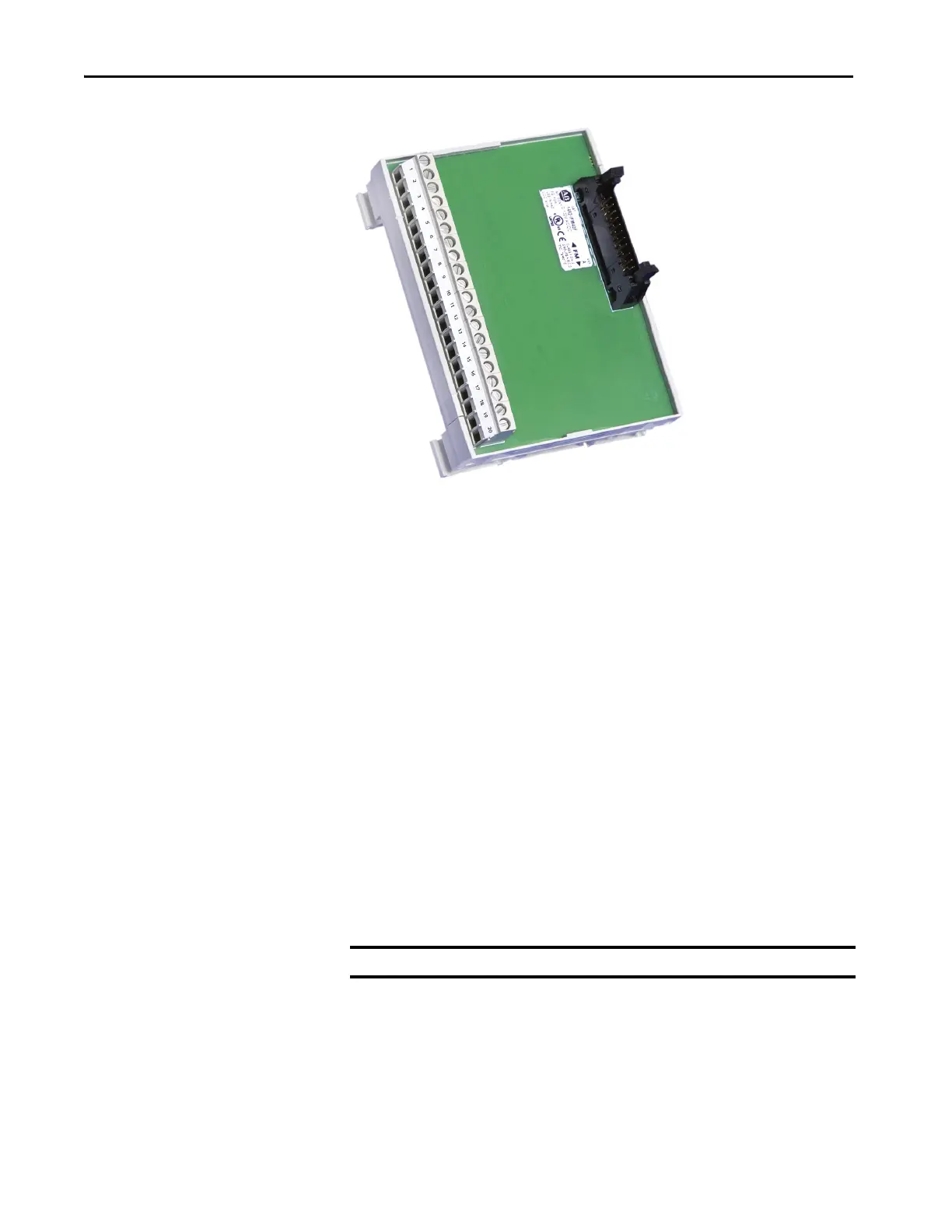
Figure 138 - 20-pin Interface Module (IFM)
Quadrature Encoder Operation
The universal encoder interface accepts either single or dual quadrature
encoders. Configure the board to accept the encoders through jumpers on J4.
Boards shipped from the factory come default to single quadrature encoder
configuration. For dual encoder configurations, the primary encoder wires to
pins 1… 7 on the 1492-IFM20 module.
To select the dual encoder option, remove the CD_QUAD jumper and place it
in PARK. This configures the board to accept two individual quadrature
encoders. In this mode, the drive can switch between encoders for applications
such as Synchronous Transfer between two motors with each having their own
encoder.
For the redundant encoder option, remove both the CD_QUAD and
POL_QRDNT jumpers and place them in PARK. With this configuration,
the drive will switch over to the redundant encoder when it detects a problem
with the primary encoder.
When the drive switches over to the redundant encoder, it cannot switch back
without recycling control power.
IMPORTANT Consult the factory for availability of dual quadrature encoder options.
 Loading...


