Rockwell Automation Publication 7000-UM202D-EN-P - May 2018 169
Control Component Definition and Maintenance Chapter 3
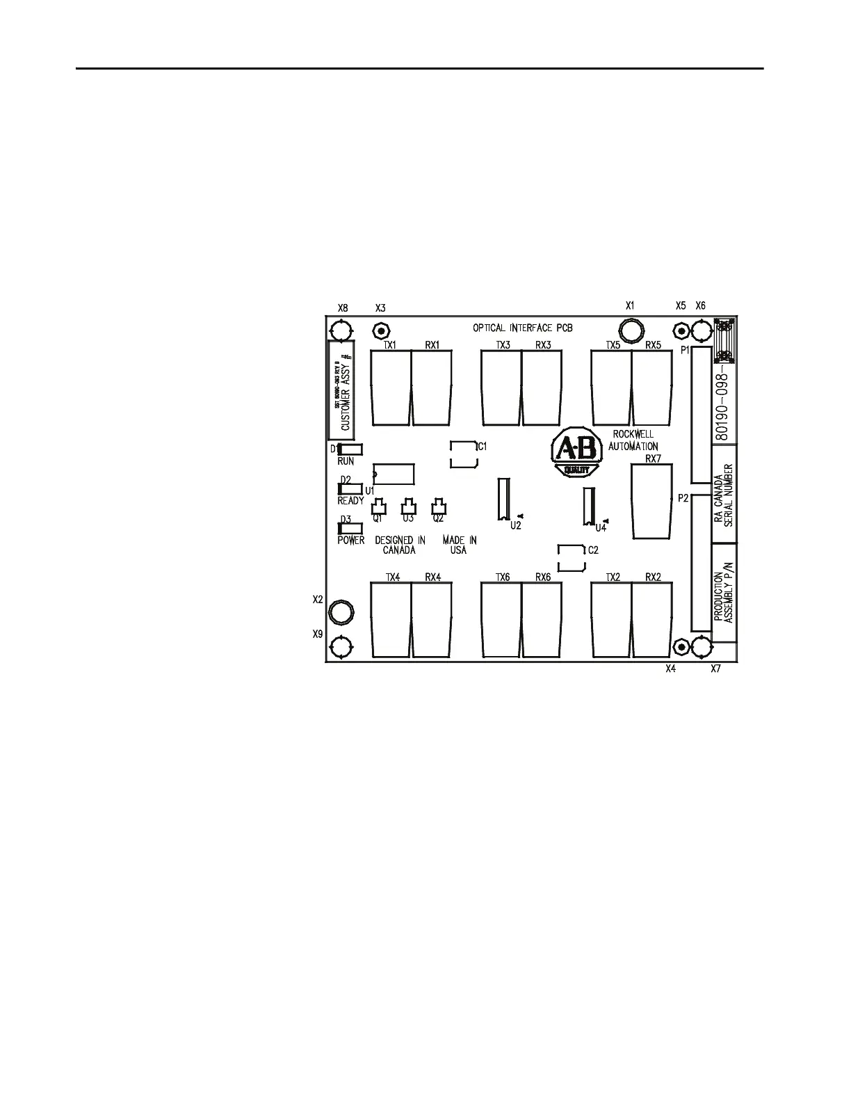
Optical Interface Boards
(OIB)
The optical interface boards are the interface between the DPM and the gate
driver circuitry. The drive control decides which device to fire, and signals the
OIB boards. The OIB board converts that electrical signal to an optical signal
that it transmits via fiber optics to the gate driver cards. Typically, the transmit
ports are gray and the receive ports are blue. The gate driver accepts that signal
and turns the device on and off accordingly. The diagnostic fiber optic signals
work the same way, but the source is the gate driver boards and the destination
is the drive control boards. Each OIB contains one extra fiber optic receiver
(RX7), which is used for temperature measurement.
Figure 140 - Optical Interface Board
The OIB boards mount directly onto the optical interface base board (OIBB)
using two parallel 14-pin connectors for the electrical connection, and plastic
clips to provide the mechanical strength. There is one OIBB for the inverter,
and one OIBB for the rectifier device. The OIBB interface to the DPM using
two ribbon cables to connect to J11 and J12.
Each OIB board can handle the firing and diagnostic duplex fiber optic
connector for six devices, whether they are SCRs or SGCTs. Physically, on the
OIBBs, there is provision for 18 devices for the inverter and the rectifier. The
top OIB board on the OIBB is for the ‘A’ devices, the middle OIB board on the
OIBB is for the ‘B’ devices, and the bottom OIB board on the OIBB is for the
‘C’ devices. Test points for the OIB gating diagnostic and temperature
feedback signals are on the OIBB.
 Loading...


