Rockwell Automation Publication 7000-UM202D-EN-P - May 2018 109
Power Component Definition and Maintenance Chapter 2
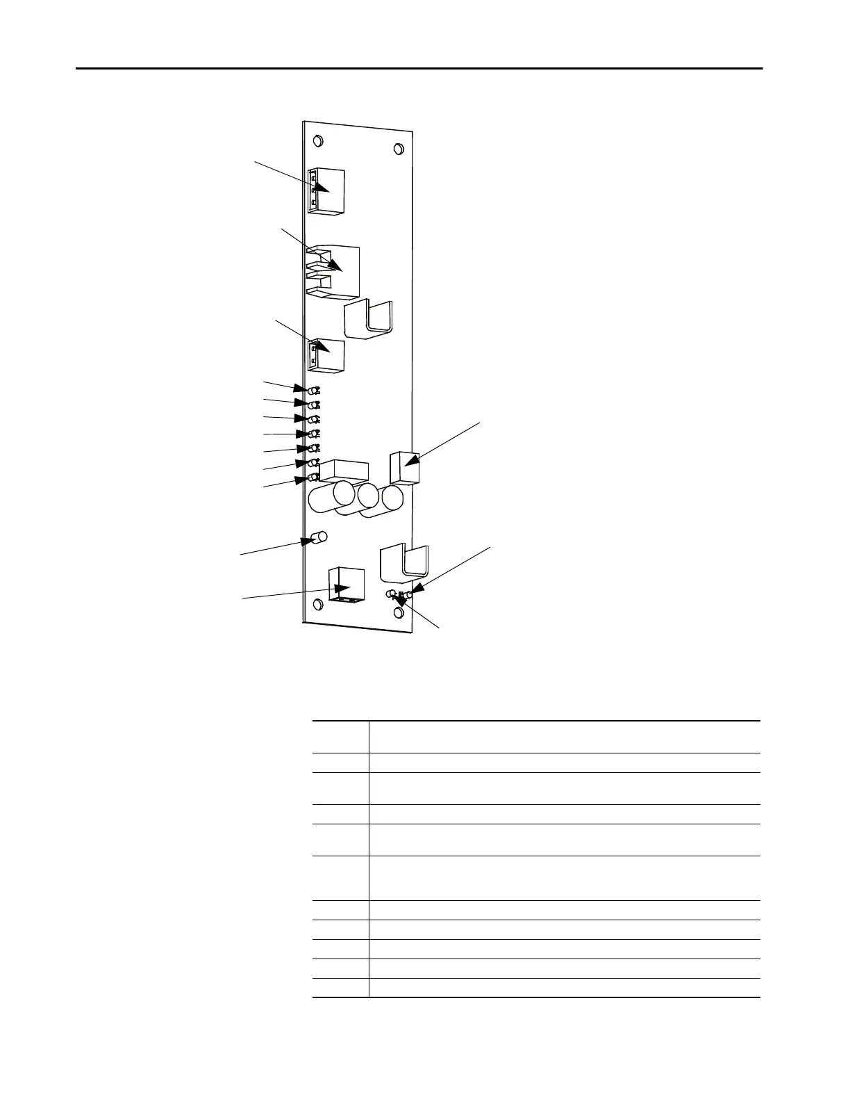
Figure 93 - Self-Powered Gate Driver Board
Terminal/Connections
TB3 - Test Power Connection
OP1, OT1 - Fiber Optic Transmitter and Receiver
TB2 - Temperature Sensor Power Connection
TP9
TP8
TP7
TP6
TP5
TP4
TP3
Status Indicator
TB1 - Snubber Connection
TB4 - Gate and Cathode
Thyristor Connection
TP2
TP1
TB1-1 Connection to SCR snubber circuit (capacitor connection end) used to extract energy from the
snubber for SPGDB operation.
TB1-2 Connection to SCR sensing resistor which indicates conduction status of SCR being operated.
TB2-1 Positive 20V power supply connection to temperature sensor board. Provides power to temperature
sensor board.
TB2-2 Common connection of positive 20V power supply to temperature sensor board.
TB3-1 Positive 15V power supply connection for test power used when commissioning drive or testing
SPGDB.
TB3-2 Provides artificial sense voltage signal to allow SPGDB to gate the SCR when in test mode. When the
appropriate test power cable is used, P/N 80018-298-51, this input is shorted to TB3-1 to obtain the
sense voltage.
TB3-3 Common connection of positive 15V power supply used for test power
TB4-2 Cathode connection to SCR being controlled
TB4-1 Gate connection to SCR being controlled
OP1 Blue fiber optic cable receptacle – gating pulse command from the processor
OT1 Grey fiber optic cable receptacle – diagnostic status of the SCR

 Loading...


