Rockwell Automation Publication 7000-UM202D-EN-P - May 2018 151
Control Component Definition and Maintenance Chapter 3
7. Remove the drive processor module from the four, 34-pin female
connectors and one, 16-pin female connector on the ACB.
8. Remove the DIM module from the DPM and plug it on the new DPM
before replacing the DPM.
9. Reverse steps 7 – 3 to re-install the boards into the low voltage control
cabinet.
10. Apply control power to the drive. The DPMs ship without installed
firmware, so the drive will shift into download mode. Install firmware in
the drive by following the guidelines the installation manual.
11. Program the drive. See publication 7000-TD002
. Save the parameters to
NVRAM and externally, using the options described earlier in this
section.
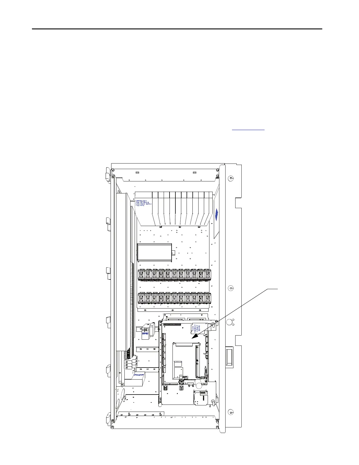
Figure 129 - ACB and DPM Replacement
Analog Control Board
(ACB)

 Loading...


