106 Rockwell Automation Publication 7000-UM202D-EN-P - May 2018
Chapter 2 Power Component Definition and Maintenance
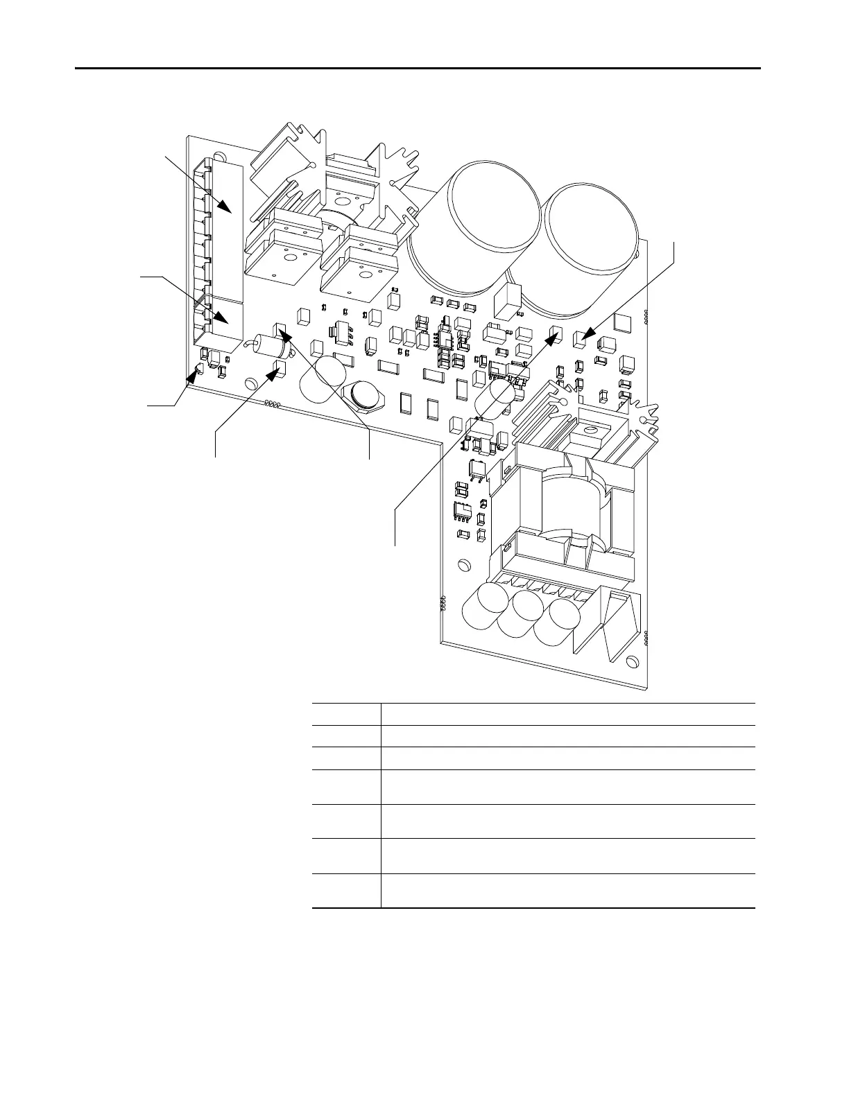
Figure 92 - SPS Board Test Points
TP6-300V
DC common
TP4-300V DC
TP14 - 20V DC COM
TP15 - 20V DC
DS1-20V DC
Good LED
J1 Snubber and
Test Power Harness
J2-20V DC
Output Power
to SGCT and
TFB Board
Terminal Connections
J1 – 1 Connection to the SGCT snubber capacitor at CS-2 location
J1 – 2 Connection to SGCT cathode terminal
J1 – 3 Connection to input attenuated feedback
(Short J1-3 to J1-4 to disable input SCR clamp stage for test power usage)
J1 – 4 Connection to 300V DC common connection
(Short J1-3 to J1-4 to disable input SCR clamp stage for test power usage)
J1 – 5 Connection to 300V DC internal bus
(Short J1-5 to J1-6 to allow input to operate from 90V AC)
J1 – 6 Connection to TOPSwitch programming resistor
(Short J1-5 to J1-6 to allow input to operate from 90V AC)
 Loading...


