Rockwell Automation Publication 7000-UM202D-EN-P - May 2018 111
Power Component Definition and Maintenance Chapter 2
20. Remove the jumper between TB3-1 and TB3-2.
21. Apply a constant fiber optic signal to the OP1 input.
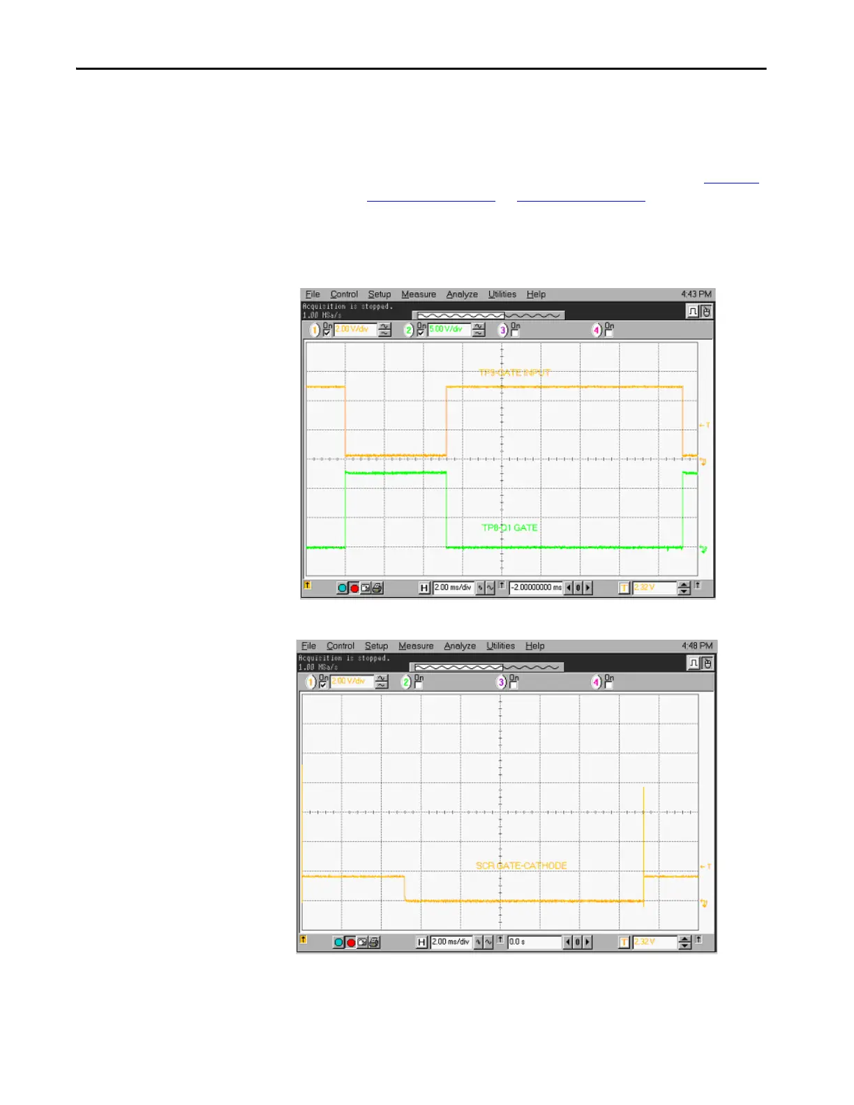
22. Apply a 60 Hz, 33% duty cycle signal, at a 0 to +2V level, between the
TB1-2 input and COM. Verify the signals as illustrated from Figure 95
to Figure 98 on page 113
. In Figure 98 on page 113, there should be a
220 µS, +/-20 µS time between the rising edge of the U4-pin7 pulse and
the falling edge of the TP7 signal.
Figure 94 - Gating Pulses
Figure 95 - SCR Gating Pulses

 Loading...


