Rockwell Automation Publication 7000-UM202D-EN-P - May 2018 41
Power Component Definition and Maintenance Chapter 2
The fuses are E-rated, current-limiting fuses with a high interrupting rating.
Because they are current-limiting, they limit both the magnitude and duration
of fault currents. They are small dimension, ferrule-type fuses with a fiberglass
body, and mount in standard fuse clips.
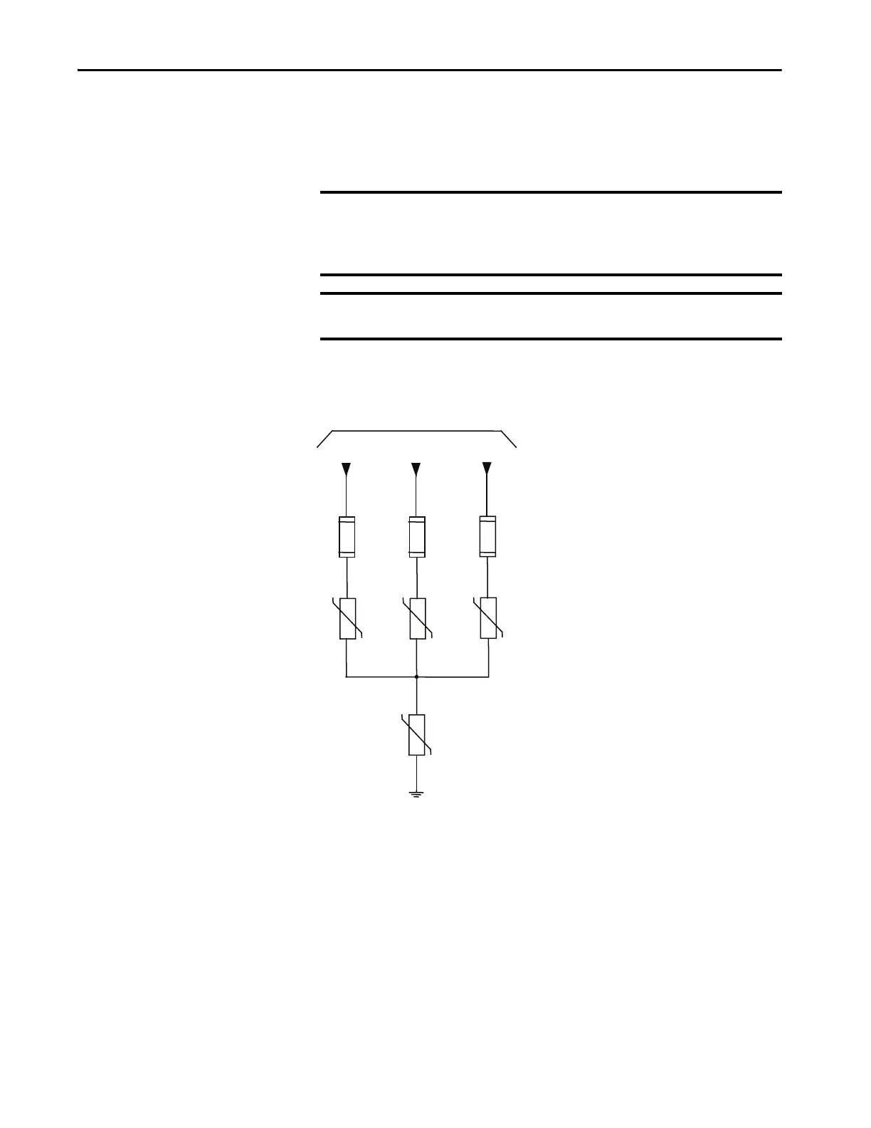
Figure 29 - Simplified Wiring Diagram
IMPORTANT Rockwell Automation selects the fuses sent with the transient suppression
network based on their characteristics (including internal resistance) for
optimum MOV performance and protection. Do not substitute other fuses
without contacting the factory first.
IMPORTANT Voltage sensing occurs after the MOV fuse and will detect open fuses in the
drive control as a master or slave undervoltage or unbalance.
Drive Input Power from Line Terminals
Transient Suppression Network
Medium Voltage Input Fuses
Phase MOV Suppressor
Ground MOV Suppressor
 Loading...


