Rockwell Automation Publication 7000-UM202D-EN-P - May 2018 47
Power Component Definition and Maintenance Chapter 2
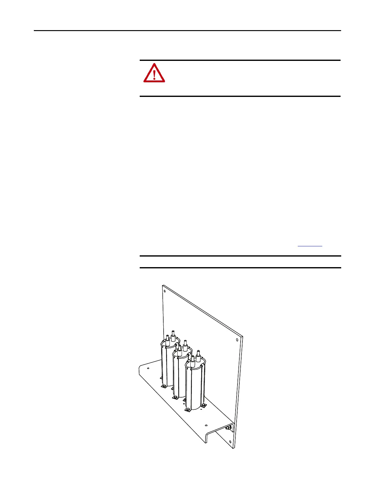
Replacing Grounding Network Capacitors
PowerFlex 7000 18-pulse and select AFE drives come with an installed
grounding network.
The number of capacitors varies depending on the system voltage.
1. Isolate and lock out all power to the drive.
To access the grounding network in an arc resistant drive, barriers
behind the swing-out LV compartment require removal.
2. Note the position of the leads.
3. Remove the 6.4 mm (¼ in.) hardware and disconnect the leads
connected to the terminals.
4. Four brackets secure the capacitor. Loosen the four screws at the base of
the brackets and lift the capacitor out.
5. Place the new capacitor and tighten the screws securely.
6. Replace the ring lugs and 6.4 mm (¼ in.) hardware (see Figure 33
).
Figure 34 - Capacitor in Grounding Network
ATTENTION: To prevent electrical shock, disconnect the main power before
working on the drive. Verify that all circuits are voltage-free using a hot stick
or appropriate voltage-measuring device. Failure to do so may result in injury
or death.
IMPORTANT The maximum torque for the capacitor terminal is 3.4 N•m (30 lb•in).

 Loading...


