Rockwell Automation Publication 7000-UM202D-EN-P - May 2018 69
Power Component Definition and Maintenance Chapter 2
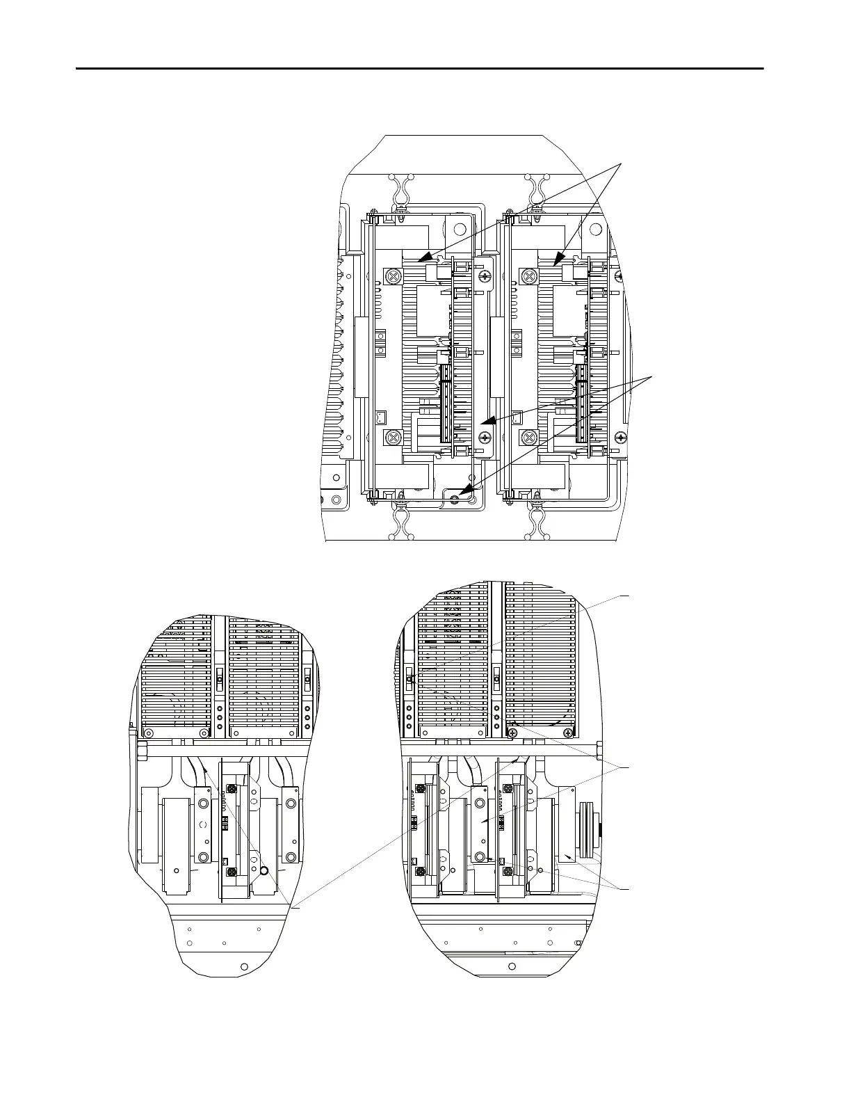
Figure 55 - Resistance Measurements SGCT PowerCage Module (with SPS Board Mounting
Assembly)
Figure 56 - Resistance Measurements (Heatpipe Model)
Resistance value between
two heatsinks is sharing
resistance in parallel with
anode-cathode resistance
Resistance value
between heatsink and
test point is snubber
resistance
Snubber Test Point
Resistance between
heatsink and test point
is snubber resistance
Resistance between
two heatsinks is
sharing resistance in
parallel with anode-
cathode resistance
End Position Heatpipes are
assembled in the PowerCage
with the Cooling Coil Facing
the device
End Position Heatpipe as show
assembled in the left side of PowerCage
End Position Heatpipe as show assembled
in the right side of PowerCage

 Loading...


