Rockwell Automation Publication 7000-UM202D-EN-P - May 2018 79
Power Component Definition and Maintenance Chapter 2
6. Use silicone gel to secure the snubber resistor assembly to the
PowerCage module. The gel minimizes possible damages to the resistor
bank during transportation from the factory. You do not need to reapply
any gel when inserting the new resistor bank. Remove the resistor bank
from the PowerCage module.
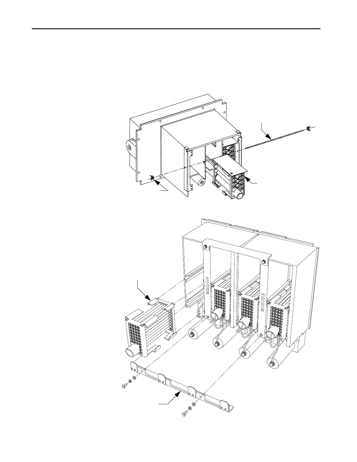
Figure 68 - Removing Resistor Bank from PowerCage Module
Figure 69 - Removing Resistor Bank from PowerCage Module (Heatpipe Model)
Push Nut
Resistor
Bank
Retaining Rod
Resistor Bank
Resistor Retaining
Bracket

 Loading...


