Rockwell Automation Publication 7000-UM202D-EN-P - May 2018 81
Power Component Definition and Maintenance Chapter 2
3. Remove the push nuts on the end of the retaining rod. Pinch the clip
together and pull off. Pull out the retaining rod.
4. Remove two bolts and swing out the plug-in stab assembly.
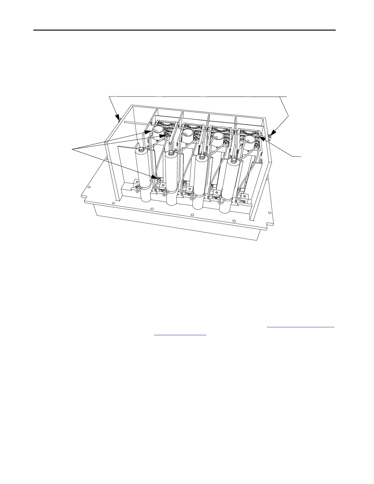
Figure 71 - Snubber Capacitor Replacement
5. Remove the capacitor from the PowerCage module.
6. Place the new capacitor back into the PowerCage module.
Ensure the bottom lead of the capacitor is on the stud.
7. Slide the retaining rod into place and push the clips back into place.
8. Connect the top lead to the capacitor.
9. Install the PowerCage module as outlined in Removing the PowerCage
Module on page 103.
1. Detach leads of
resistor assembly
2. Pinch and remove
clips at end of retaining
rod
3. Extract
retaining rod

 Loading...


