290 Rockwell Automation Publication MOTION-UM003K-EN-P - January 2019
Chapter 14 Status, Faults, and Alarms
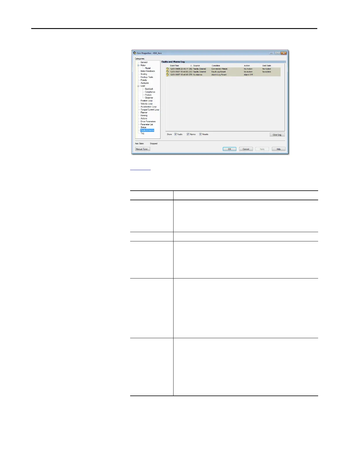
Figure 107 - Faults and Alarms Log
Table 63 describes the parameters for the Faults and Alarms dialog box.
Table 63 - Faults and Alarms Dialog Box Descriptions
Parameter Description
Indicator Displays the following icons to indicate the state of a fault or alarm:
•Alarm On
•Alarm Off
•Fault Occurred
• Reset Occurred
Date/Time Displays the date and time the event occurred. The time stamp is the workstation setting.
Source Displays the source of the event, for example:
•Safety Fault
• Module Fault
•Group Fault
• Axis Fault
• Axis Alarm
Condition Displays detailed information specific to the event category and code.
For drive exception conditions, the information is the same text that is used for the
condition. This field can contain more information when the Subcode field has been used
for that entry. The field is a more detailed entry if both codes are used in the log, for
example:
• Group Sync Failure
• Bus Overvoltage UL
• All Axis Faults
• Motor Overspeed
• Axis Init Fault
Action Displays the action command that was executed in response to the event as configured in
the axis. For instance, in many cases this display indicates that a command sent to a
drive, for example:
• Planned Stop
• Ramped Stop
• Limited Stop
•Coast
• No Action
•Alarm Off
•Alarm On
 Loading...


