Driving Equipment
ØThe Directional Control Lever (located on the top right side of the dash) controls the direction
of travel - forward, reverse and neutral (free-wheeling). Select the direction of travel desired. The
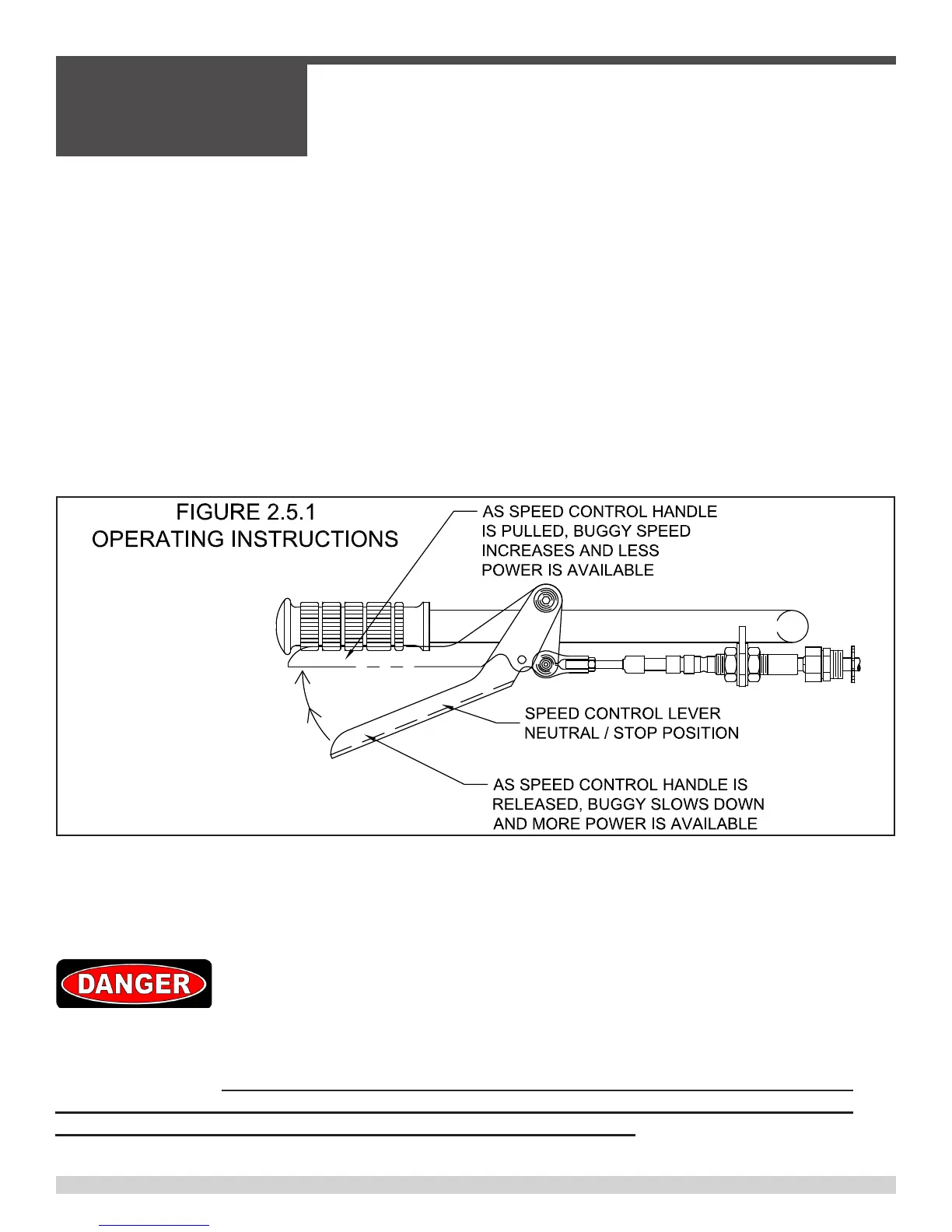
Speed Control Lever (located on the right side of the handle bar) controls the vehicle speed,
power, and dynamic hydraulic braking.
IMPORTANT OPERATOR NOTE: When starting from a stop, steadily pull the Speed Control
Lever towards the hand grip. The more the Speed Control Lever is squeezed towards the hand
grip the faster the buggy will move. Position the Speed Control Lever where the engine does not
lug to achieve maximum speed or power depending on job site conditions. Do not use the engine
rpm speed to control buggy speed. Letting the Speed Control Lever return to the neutral position
will slow the buggy (by means of dynamic hydraulic braking) and increase power at the drive
wheels, acting as a “downshift”
ØTo slow and/or stop vehicle:
• Release Speed Control Lever.
• Service brake pedal (located at right of stand-on platform) may be pushed down to acti-
vate service brake and assist in slowing the vehicle.
• Avoid sudden stops whenever possible.
In all cases, upon release of the speed control lever, the speed control linkage should
operate smoothly and freely and completely stop machine travel within 6’ – 8’ in both for-
ward and reverse. If the speed control linkage does not operate smoothly and freely and/
or does not automatically stop machine travel upon release of the speed control lever,
then remove machine from service until repairs have been made.
2.5 - Operating Instructions
SECTION 2
OPERATIONS
055838 Page 42