22
33
32
12
21
27
8
18
28
23
24
RETURN BUCKETDUMP BUCKET
30
25
15
24
23
13
26
29
CUT ONE SIDE OF RU
BBER BUSHING THRU
AND INSTALL CABLE 22.
IN THE TOP OF
CONSOLE #42100-38 TO THE
RIGHT OF REAR WHEEL
STEERING ASSEBMBLY.
MOUNT LOOM CLAMP O
N CARBURETOR STUD T
O RETAIN CABLE.
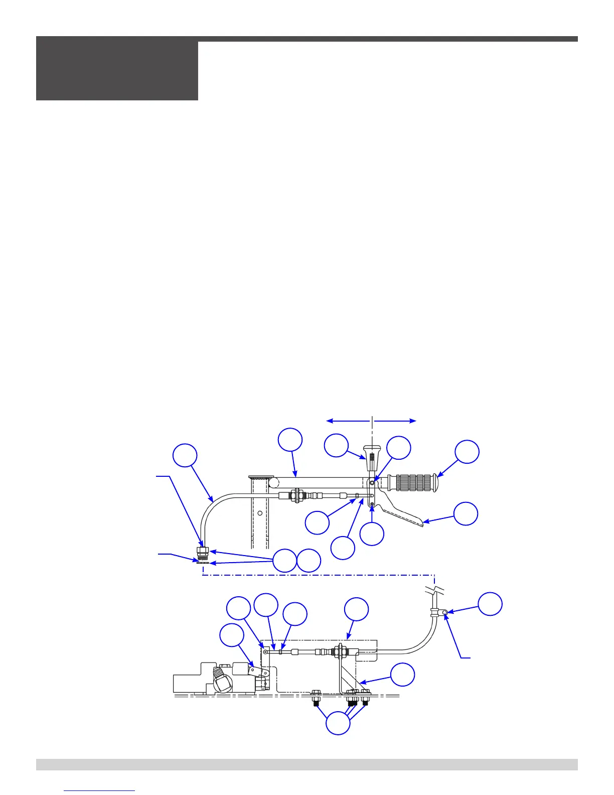
h) Install one (1) 1/4” NF-28 jam nut on each end of shift cable. Thread both nuts to
back end of threaded rod.
i) Insert bulkhead fittings on control cable into their respective mounting holes on the
handlebar (item 12) and dump valve mounting bracket (item 15).
j) Place a 5/8”NF-18 jam nut on the threaded end of the bulkhead fitting protruding
through each mounting hole.
k) Attach a clevis to each end of the cable.
Note: In all cases the cable attachments must be threaded onto the ¼”NF-28 cable
end one-quarter of an inch(¼”). After each attachment is threaded onto the cable
end its position must be secured by tightening the jam nut (item 24) against the clevis.
l) Then attach the cable end clevises to the handle mounted dump control lever
(items 14 and 18) and the dump valve connecting link bar (item 13) using the Clevis
Pins. Secure the clevis pins in the clevises with NEW 3/32”(.093”) diameter x 3/4”
long plated cotter pins. Do not reuse cotter pins.
m) Tighten the two (2) 5/8”NF-18 jam nuts on the cable bulkhead fitting at the
mounting hole located at the dump valve connecting link bar. Adjust and tighten the
nuts so that dump valve connecting link bar (item 13) is in the vertical position.
n) Tighten the two(2) 5/8”NF-18 jam nuts on the cable bulkhead fitting on the han-
dlebar. Adjust the nuts so the handlebar mounted dump handle is in the vertical
position.
3.6 - Dump Lever Adjustment, continued
SECTION 3
SERVICE
055838 Page 60