16
•
MN-35947
•
Rev 15
•
01/18
•
Combitherm® CT PROformance™ and CT Classic Series Installation Manual
#432 - 01/18 DUE TO ONGOING PRODUCT IMPROVEMENT, SPECIFICATIONS ARE SUBJECT TO CHANGE WITHOUT NOTICE. WWW.ALTO-SHAAM.COM
ELECTRICAL - CTP10-10G
(DEDICATED CIRCUIT REQUIRED)
WITH COMBISMOKER
®
OPTION
VOLTAGE PH HZ AWG (mm
2
)
CONNECTION
no cord, no plug
AMPS BREAKER kW
CONNECTION
no cord, no plug
AMPS BREAKER kW
✑ ✎ ▲
120 1 60 12 (3.31) L1, L2/N, G 6.8 20 .84 L1, L2/N, G 12.0 20 1.5
✑ ✒ ▲
208 – 240
1
✝
50/60 14 (2.08) L1, L2/N, G 4.8 – 4.2 15 1.0 L1, L2/N, G 7.3 – 7.1 15 1.5 – 1.7
✑ ✒ ▲
208 – 240 3 50/60 14 (2.08) L1, L2, L3, G 4.8 – 4.2 15 1.0 L1, L2, L3, G 7.3 – 7.1 15 1.5 – 1.7
✒
380 – 415 3 50/60 14 (2.08) L1, L2, L3, N, G 4.6 – 4.2 15 1.0 L1, L2, L3, N, G 7.2 – 7.1 15 1.6 – 1.7
✎ mA ✒
✝
▲ ,
WEIGHT PAN CAPACITY STANDARD MODEL WITH COMBISMOKER
®
OPTION
NET 625 lbs (283 kg)
FULL–SIZE: 20" x 12" x 2-1/2"
GN 1/1: 530 x 325 x 65mm
**HALF–SIZE SHEET: 18" x 13" x 1"
Eleven (11)
Eleven (11)
Eleven (11)
Ten (10)
Ten (10)
Eleven (11)
SHIP 695 lbs* (315 kg*)
SHIP DIMENSIONS PRODUCT CAPACITY
(L x W x H) 56" x 45" x 65"* PRODUCT MAXIMUM 120 lb (54 kg)
(1422mm x 1143mm x 1651mm)* VOLUME MAXIMUM 75 quarts (95 liters)
* . .
UL Marked
Appliances
Maximum
Input
BTU/h
Minimum
Input
BTU/h
Maximum Inlet
Pressure
Inches WC
Minimum Inlet
Pressure
Inches WC
Maximum Fuel
Consumption*
AGA Marked
Appliances
Maximum
Input
MJ/h
Minimum
Input
MJ/h
Maximum Inlet
Pressure
kPa
Minimum Inlet
Pressure
kPa
Maximum Fuel
Consumption
CFH GPH m
3
/h L/h
Natural Gas
80,000 53,000 14.0
5.5 76.2 N/A Natural Gas
84.4 55.9 3.48
1.13 2.2 N/A
Propane 9.0 32.0 0.9 Propane 2.75 0.9 3.3
*Assumes an average heating value for natural gas to be 1050 BTU/SCF and a specifc gravity
of 0.60. The assumed value for propane gas is 2,500 BTU/SCF, and a specific gravity of 1.53
CE Marked
Appliances
Maximum Input Minimum Input
Nominal Gas Pressure
mbar
Maximum Gas Pressure
mbar
Maximum Fuel Consumption
m
3
kWh (Hs) kWh (Hi) kWh (Hs) kWh (Hi)
2E (G20)
23.3 21.0 15.5 14.0
20
50
2.2
2LL (G25) 20 2.6
3P (G31)
22.8 21.0 15.5 14.3
37 0.9
3B/P (G30) 29 0.9
GAS REQUIREMENTS (GAS TYPE MUST BE SPECIFIED ON ORDER) HOOK-UP: 3/4" NPT
WATER REQUIREMENTS WATER QUALITY STANDARDS
TWO (2) COLD WATER INLETS - DRINKING QUALITY*
ONE (1) TREATED WATER INLET: 3/4" NPT connection. Line pressure 30 psi minimum dynamic and
90 psi maximum static (200 to 600 kPa) at a minimum flow rate of 0.26 gpm (1 L/min).
ONE (1) UNTREATED WATER INLET: 3/4" NPT connection. Line pressure 30 psi minimum dynamic and
90 psi maximum static (200 to 600 kPa) at a minimum flow rate of 2.64 gpm (10 L/min).
* Both inlets can be from same source. Divide using a manifold. Run one side through treatment device before running to oven.
Must meet line pressure and flow rate specifications for both inlets.
WATER DRAIN: 1-1/2" (40mm) connection with a vertical vent to extend above the exhaust vent.
materials must withstand temperatures up to 200°F (93°C).
It is the sole responsibility of the owner/operator/purchaser of this equipment
to verify that the incoming water supply is comprehensively tested and
if required, a means of “water treatment” provided that would meet
compliance requirements with the published water quality standards shown
below. Non-compliance with these minimum standards will potentially
damage this equipment and/or components and void the original equipment
manufacturer’s warranty. Alto-Shaam recommends using OptiPure
®
[www.
optipurewater.com] products to properly treat your water.
Contaminant
Free Chlorine
Hardness
Chloride
pH
Silica
Total Dissolved Solids (tds)
Inlet Water Requirements
Less than 0.1 ppm (mg/L)
30-70 ppm
Less than 30 ppm (mg/L)
7.0 to 8.5
Less than 12 ppm (mg/L)
Treated line: 50-125 ppm
Untreated line: 50-360 ppm
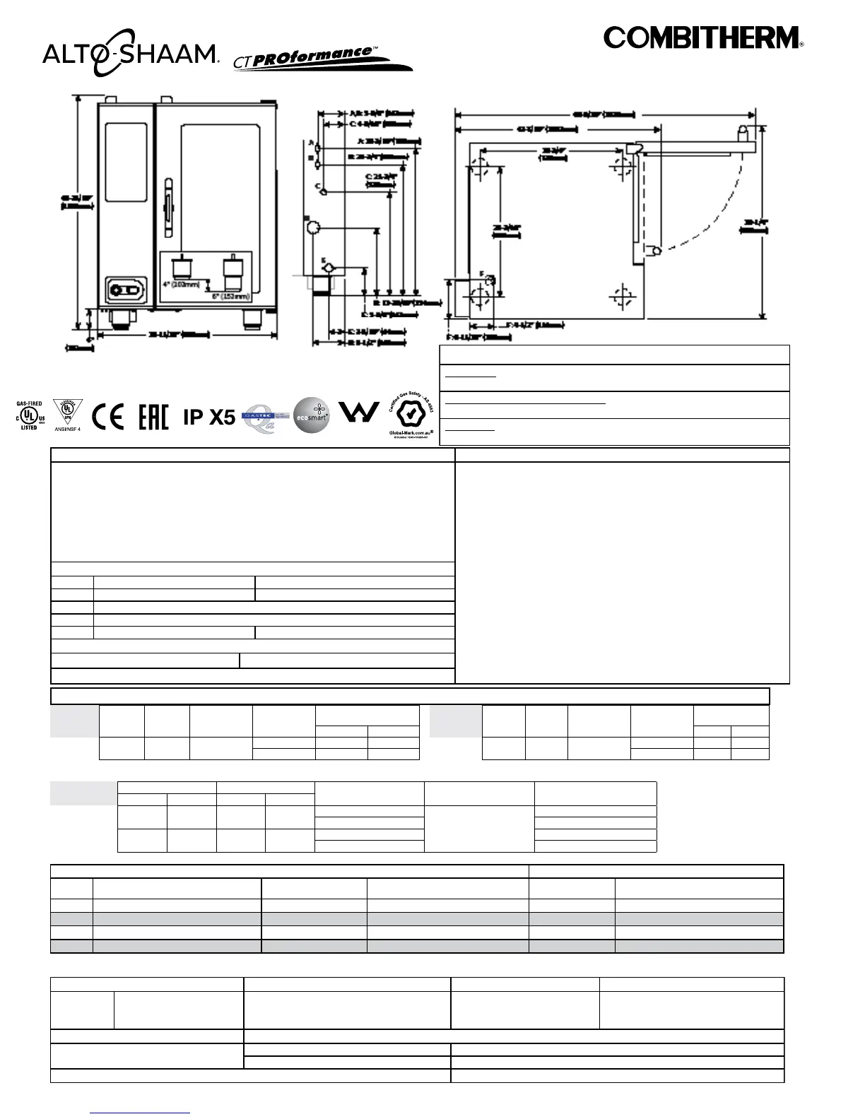
CLEARANCE REQUIREMENTS
LEFT:
0" (0mm) 18" (457mm) recommended service access
RIGHT:
0" (0mm) Non-combustible surfaces 2" (51mm) door swing or combustible surfaces
TOP:
20" (508mm) for air movement
BOTTOM:
5-1/8” (130mm) for legs, air aintake
BACK:
4" (102mm) 4-5/16” (109mm) optional plumbing kit
INSTALLATION REQUIREMENTS
• Oven must be installed level. • Hood installation is required.
• Water supply shut-off valve and back-flow preventer when required by local code.
DIMENSIONS: H x W x D
EXTERIOR:
45-11/16" x 35-11/16" x 41-7/16" (1160mm x 906mm x 1053mm)
EXTERIOR WITH RECESSED DOOR:
45-11/16" x 40-11/16" x 41-7/16" (1160mm x 1033mm x 1053mm)
INTERIOR:
31-1/2" x 16-1/4" x 28-1/16" (800mm x 411mm x 712mm)
CTP10-10G
-
WMTS 104
WM 40202
A = Treated water B = Untreated water C = Gas
D = Electrical (Back) E = Water Drain F = Electrical (Bottom)
Front
Back
Top/Bottom
 Loading...