3.8 Functional Test
CAUTION: Work carefully when performing these tests - hazardous voltages are
present on the input and output during the tests.
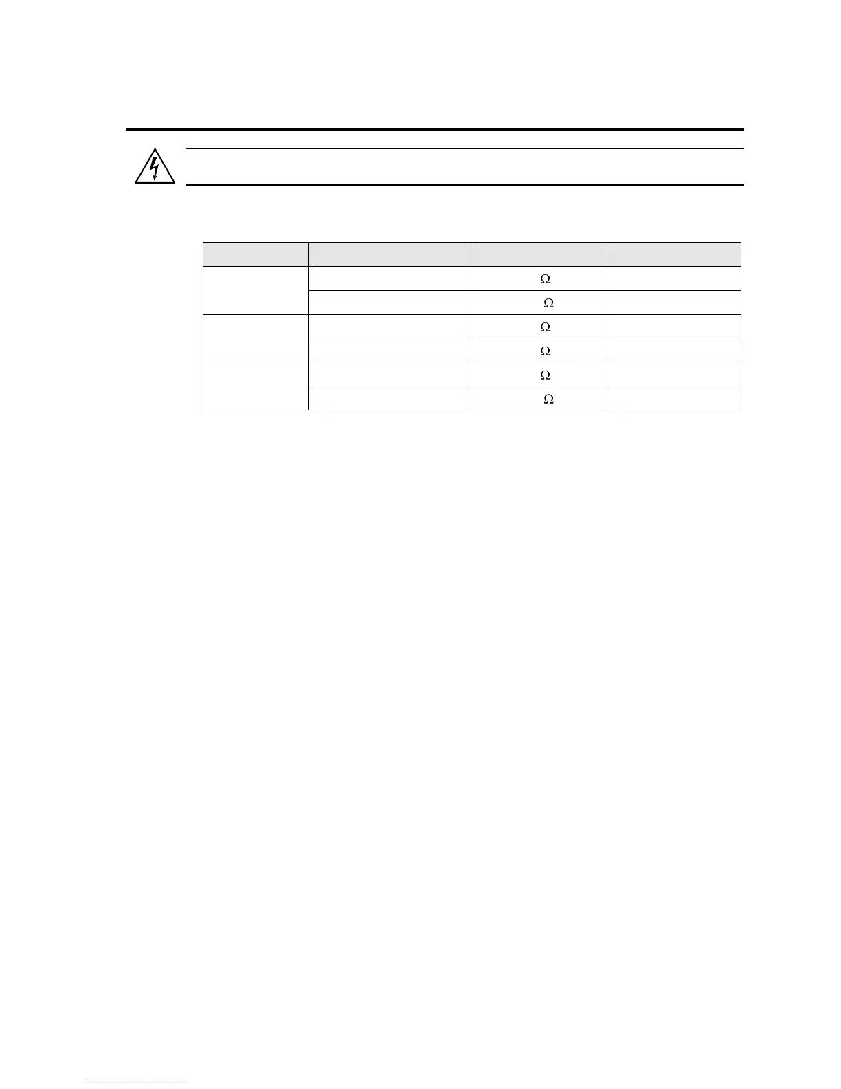
Refer to Figure 3-7 for the test setup. For -AV option units, the resistor values need to be
adjusted as follows:
1. One phase at a time, connect a voltmeter and an oscilloscope or distortion analyzer to
the AC source output at the rear panel output terminals. Connect each sense input to
the adjacent power pin on the rear panel connector.
2. Connect the AC mains voltage connections to the AC source input terminals. Turn on
the power via the front panel circuit breaker.
3. Verify that the front panel 7 segment LED displays indicate the initial start up voltage and
frequency.
4. Select the low voltage range. Set the frequency to 400 Hz with the right knob. Choose
the current function with the Select key. Set the current limit to the maximum value using
the right knob. Set the output voltage to 135 V (115 V for the –AV option, 156 V for –HV
option) with the left knob.
5. Enable the output by pressing the Output key. The green LED above the key will
illuminate when the output is on. The output should be a clean 135V (115 V for the –AV
option, 156 V for –HV option) AC sinewave having less than 2.0% distortion.
6. Apply full load (refer to table above) to the output of the source and verify the output
remains within 0.1% of the initial 135 V (115 V for the –AV option, 156 V for –HV option).
The output should still be clean and the distortion should still be less than 2.0 % at 400
Hz.
7. Using the right knob set the output current limit value to 3 amps. If the unit is configured
for Constant Current mode (factory default), the system should go into current limit and
reduce the output voltage. If the unit is configured for Constant Voltage mode, an error
message will appear on the display (err -300) that indicates an output fault condition and
the output will go off. Return the current value to the maximum current and disconnect
the load.
8. Repeat steps 4 through 7 but set the output high voltage range and the current limit to
maximum value. Refer to the table above for the relevant resistor values. For units that
are factory configured with a single voltage range, these steps do not have to be
repeated.
9. Repeat steps 1 through 7 for all three output phases.
 Loading...