6.3 Routine Calibration
Setup:
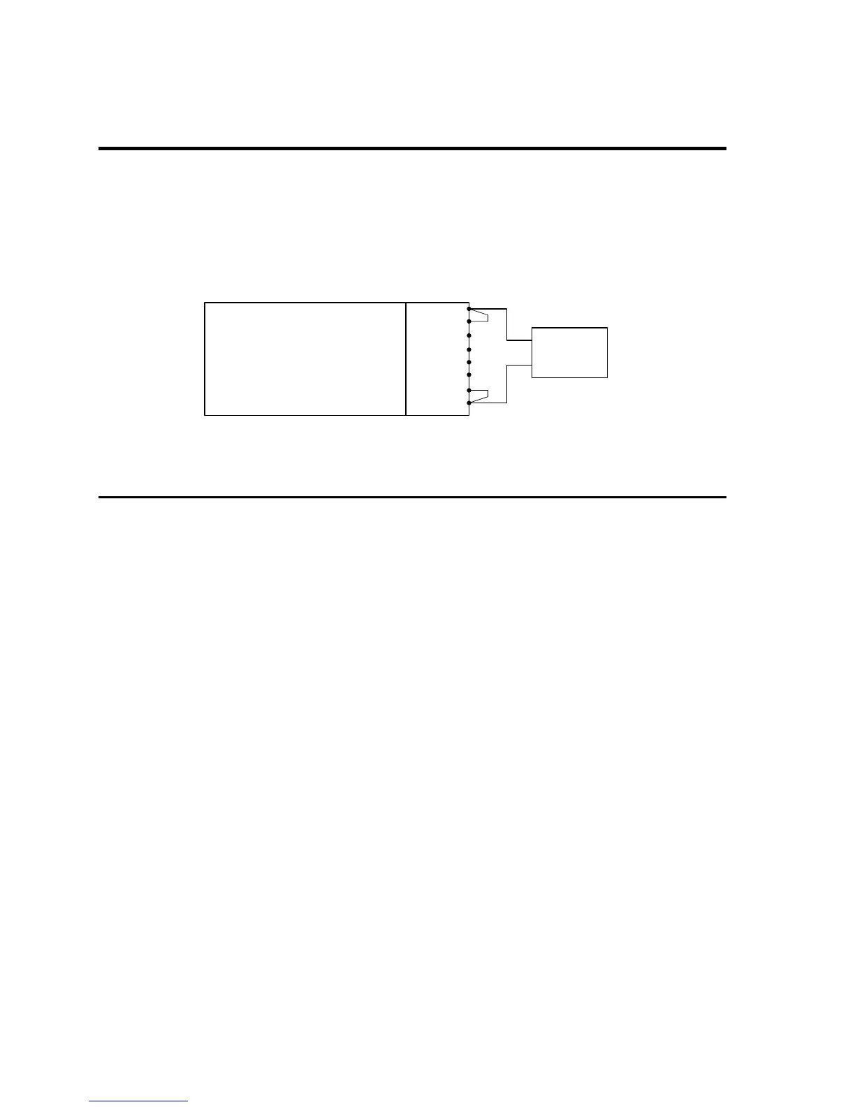
Connect the test equipment to the power source as shown in Figure 6-1. The DMM can be
connected to the common output terminal at the rear of the unit. Use the phase output for
phase A, B and then C in sequence to calibrate all three phases.
Never connect the load wire to the SENSE terminal at the Rear Panel terminal strip. The
load must be connected to the POWER output terminal and a jumper between the POWER
and SENSE terminal. Always connect the external DVM to the SENSE terminal.
Figure 6-1: Test Equipment Hookup for Routine Output and Voltage Measurement Calibration
6.3.1 Output Voltage Calibration
1. Select the high voltage range. Set the output frequency to 60 Hz (400 Hz on 2003RP-
AV). Set the output voltage to 230 volts.
2. Remove any load and enable the output voltage with the OUTPUT button.
3. Put the 2003RP in CAL mode by pressing the recessed CAL button.
4. Use the SELECT key to toggle to the output voltage calibration mode. In this mode, all
LED‟s except the PF LED are off.
5. Use the Left control knob to adjust the output voltage displayed on the external reference
DMM until it reads as close as possible to 230 V
AC
.
6. Press the CAL button to leave the calibration mode.
2003RP
AC SOURCE
Pow er A 1
Sense A 2
Pow er B 3
Sense B 4
Pow er C 5
Sense C 6
Pow er N 7
Sense N 8
DMM
AC VOLT
 Loading...