6.3.2 Measurement Calibration - Low Scale
Note: Measurement calibration can be done at any output frequency setting as
only one set of calibration coefficients is used for measurement
calibration. However, for best results, calibrate the measurements at the
frequency, which is used in most applications, e.g. 50 Hz, 60 Hz (except
model 2003RP-AV) or 400 Hz.
Refer to Table 6-1 for correct load resistors based on model number.
Low Scale Voltage Measurement Calibration
1. Connect the test equipment to the power source as shown in Figure 6-2. Do not
connect any load during this step. Voltage calibration must be done under no load
conditions.
2. Select the Low Voltage Range and program the output voltage to 10 VAC.
3. Put the 2003RP in CAL mode by pressing the recessed CAL button.
4. Use the SELECT key to select the Voltage Measurement calibration mode. This mode is
indicated by the FREQ LED.
5. Use the left control knob to adjust the voltage reading shown on the right hand 7
segment LED until it reads as close as possible to the reference reading as displayed on
the external DMM2.
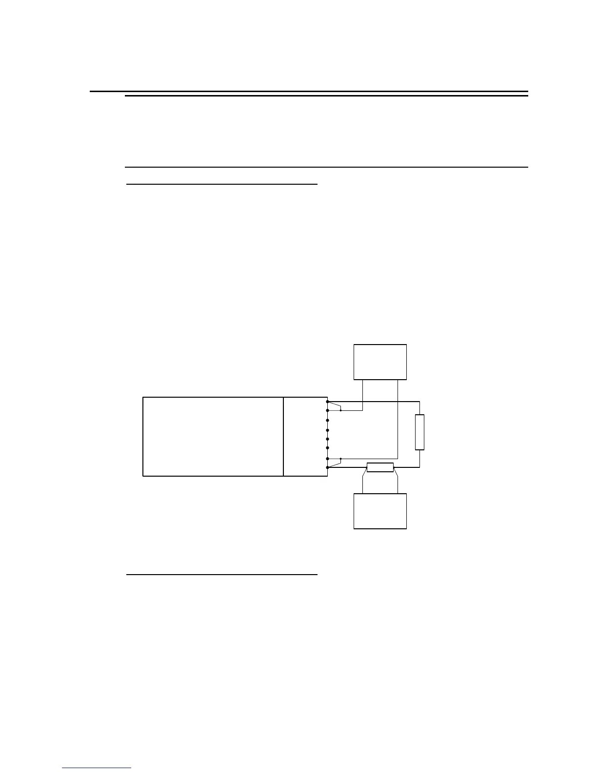
Figure 6-2: Test Equipment Hook-up for Current and Power Measurement Calibration
Low Scale Current Measurement Calibration
1. Connect the test equipment to the power source as shown in Figure 6-2.
2. Apply the resistive load (see Table 6-1 for model and load) to the output terminals. Make
sure external DMM1 used for current measurement is across the shunt.
3. The output voltage must be programmed to 10.0 volts.
4. Use the SELECT key to select the Current Measurement calibration mode. This mode is
indicated by the I RMS LED.
5. Use the left control knob to adjust the current reading shown on the right hand 7 segment
LED until it reads as close as possible to the reference reading indicated by the DMM
2003RP
AC SOURCE
Pow er A 1
Sense A 2
Pow er B 3
Sense B 4
Pow er C 5
Sense C 6
Pow er N 7
Sense N 8
DMM 2
AC VOLT
DMM 1
AC VOLT
0.1 ohm Shunt
Load Resistor

 Loading...