Pinouts
Appendix B
B-1
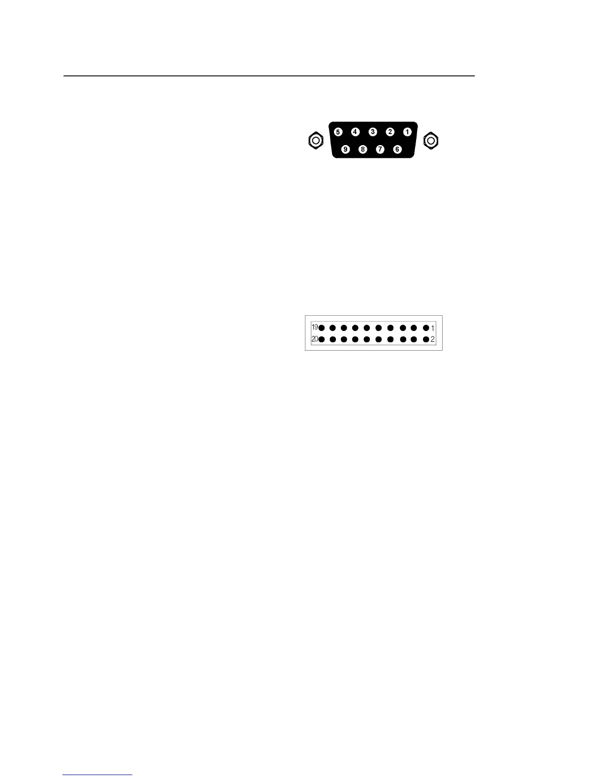
B.1 RS232 Connector Pinout
Figure B-1, RS232 Connector (Female)
Pin Function Description
2 RXD Data In
3 TXD Data Out
5 GND Signal Ground
7 RTS Request to Send - always +12 V
All other pins are not connected
B.2 Digital I/O Port Connector
Figure B-3, Digital I/O Port Connector
8-bit TTL-compatible port. Each bit is configurable as an input or output. If
configured as an output, the bit status can be set, and if configured as an input it can
be read, from the front panel or via the computer interfaces.
When set as an output, each line can drive three LSTTL loads. When set as an input
each input presents one LSTTL load. The connector will mate with a 20-pin IDC
header plug (not supplied). The pinout is as follows:-
Pin Function
1 Ground
2 Ground
3 D0
4 Ground
5 D1
6 Ground
7 D2
8 Ground
9 D3
10 Ground
11 D4
12 Ground
13 D5
14 Ground
15 D6
16 Ground
17 D7
 Loading...