Chapter 5, WEB CONTROL PANEL OPERATION
5-22
Slope
The roll-off of the output filters is set, using this control, to values from 6 dB to
24 dB/octave, in 6 dB steps. Note that there are some restrictions in that it is not
possible to select 18 or 24 dB/octave settings at Time Constants of 500 ms or shorter
when using the fast time constant mode.
X Offset and Y Offset
These controls allow manual adjustment of the X1 channel and Y1 channel output
offsets. The offset level set by the controls, which can be any value between -300%
and +300% in 0.01% steps, is added to the X1 channel or Y1 channel output when
the corresponding check boxes are checked.
The values are also set automatically and turned on by the Auto-Offset function,
which is activated by clicking the Auto Offset button.
Auto Offset
This button adjusts the X1 offset and Y1 offset values so that the X1 channel and Y1
channel outputs are zero. Any small residual values can normally be removed by
calling Auto-Offset for a second time after a suitable delay to allow the outputs to
settle.
Noise Measurement
This control is used to configure the instrument for noise measurements. When
checked, the available output time constant is restricted to the values in the range
500 µs to 10 ms inclusive, since it is only at these values that the noise
measurements are calibrated, and the synchronous time constant control is turned
off.
The output filter slope is also restricted to either 6 or 12 dB/octave.
When the control is unchecked then the instrument is configured for normal lock-in
amplifier operation.
Noise Buffer LengthThis control, which is only active when the above Noise
Measurement control is checked, sets the averaging time of the buffer used to
determine the mean value of the output signal when making noise measurements.
Settings of Off, 1 s, 2 s, 3 s and 4 s can be selected.
The operation of this feature is described in more detail in section 3.3.20
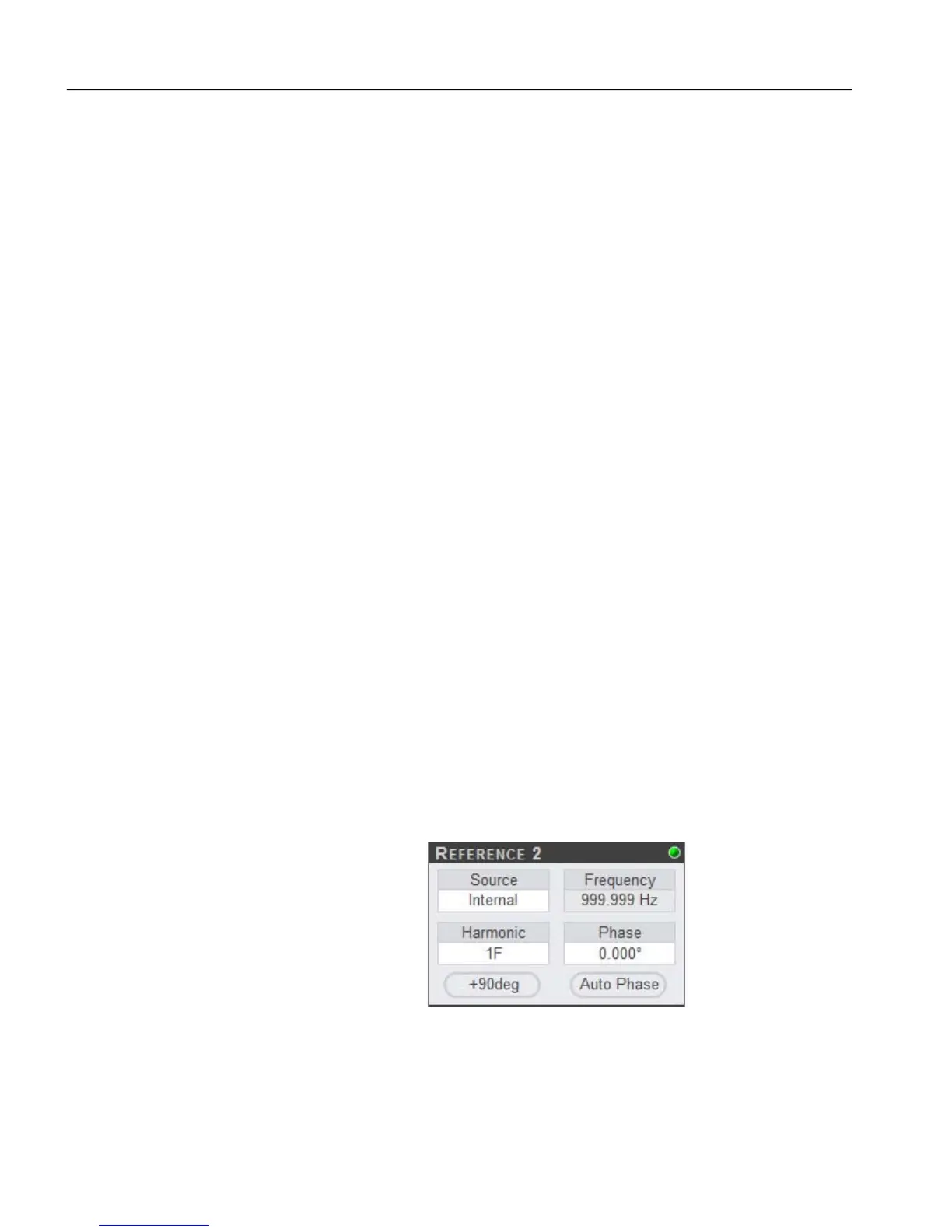
5.3.07 Main Controls: Reference 2
Figure 5-25, Main Controls: Reference 2
When the Demodulator is set to Dual mode, the Reference 2 controls section of the
panel, shown in figure 5-25, is active. These controls affect the second set of
demodulators.