Chapter 5, WEB CONTROL PANEL OPERATION
5-36
Equation 2 DAC Voltage
+10000 10.0 V
0 0.0 V
-10000 -10.0 V
User setting
When User setting is selected the corresponding DAC connector on the rear
panel of the instrument outputs the voltage set by the corresponding control, in
the range 10.000 V.
Digital Sig Mon
When set to the Digital Sig Mon setting the corresponding DAC connector on
the rear panel of the instrument outputs a voltage representing the digital output
of the main signal channel ADC
Digital Sig Mon2
When set to the Digital Sig Mon2 setting the corresponding DAC connector on
the rear panel of the instrument outputs a voltage representing the digital input to
the second demodulator.
ADC1 Monitor
When set to the ADC1 Monitor setting the corresponding DAC connector on the
rear panel of the instrument outputs a voltage representing the voltage at the rear-
panel ADC1 input connector.
Sync Osc
When set to the Sync Osc setting the corresponding DAC connector on the rear
panel of the instrument outputs a voltage representing the sinusoidal waveform
applied to the first in-phase demodulator. If the reference mode is external, this
allows generation of a sinusoidal signal that is phase locked, and with adjustable
phase relationship, to it.
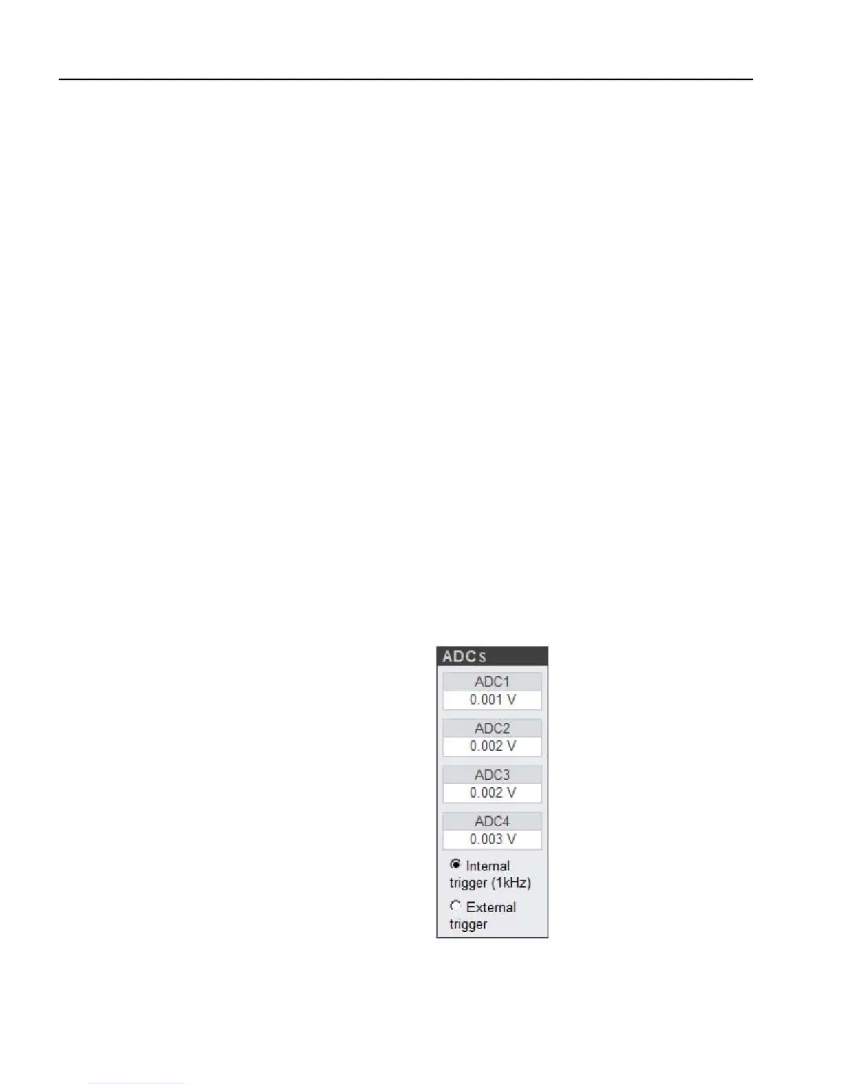
5.3.18 Rear Panel: ADCs
Figure 5-35, ADC Indicators
The ADCs indicators show the voltages present at the instrument’s rear-panel ADC1
 Loading...