Chapter 5, WEB CONTROL PANEL OPERATION
5-33
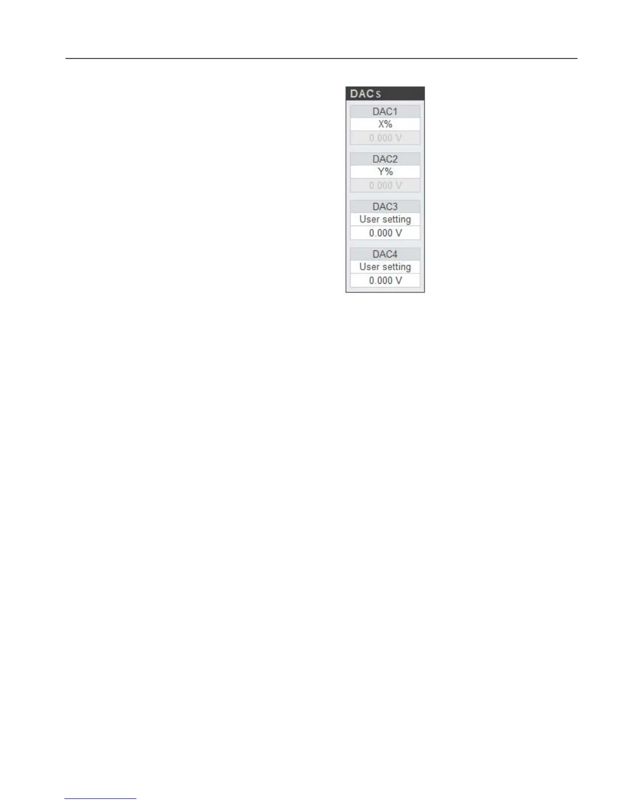
5.3.17 Rear Panel: DACs
Figure 5-34, DACs Controls
These controls, shown in figure 5-34, are used to configure the signals that will
appear on the four DAC connectors on the rear panel of the instrument. Each control
has a signal selector; if this is set to User setting then the text box below is used to
specify the corresponding voltage; otherwise it is grayed out.
The controls operate as follows:
DAC1, DAC2, DAC3, and DAC4
These four controls select which signal will be made available at the corresponding
DAC 1 to DAC 4 connectors on the rear panel of the instrument. The following
settings are available, but note that internal connection limitations mean that not all
settings are available for each DAC connector.
X% (2.5V fs)
In this setting the corresponding DAC connector on the rear panel of the
instrument outputs a voltage related to the X1%fs display as follows:-
X1% DAC Voltage
+300 7.5 V
+100 2.5 V
0 0.0 V
-100 -2.5 V
-300 -7.5 V
Y% (2.5V fs)
In this setting the corresponding DAC connector on the rear panel of the
instrument outputs a voltage related to the Y1%fs display as follows:-
Y1% DAC Voltage
+300 7.5 V
+100 2.5 V
0 0.0 V
-100 -2.5 V
-300 -7.5 V