Chapter 5, WEB CONTROL PANEL OPERATION
5-15
5.3.02 Main Controls: Display Indicators
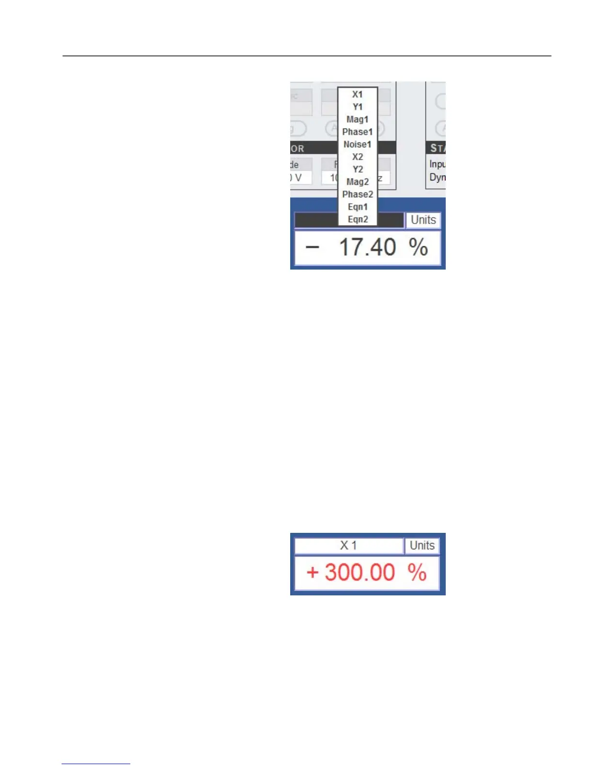
Figure 5-18, Selecting Instrument Outputs
Each of the four digital indicators along the bottom of the screen can be set to
display the following instrument outputs (see figure 5-18).
Output Description
X1 X1 channel output. In Single Reference mode this is the X output
Y1 Y1 channel output. In Single Reference mode this is the Y output
Mag1 Resultant (Magnitude1) output. In Single Reference mode this is the Mag
output
Phase1 Phase1 output. In Single Reference mode this is the Phase output
Noise1 Noise output for the first demodulator.
X2 X2 channel output, valid only in when demodulator 2 is active
Y2 Y2 channel output, valid only in when demodulator 2 is active
Mag2 Resultant (Magnitude2) output, valid only in when demodulator 2 is
active
Phase2 Phase2 output, valid only in when demodulator 2 is active
Eqn1 Output value of User Equation 1
Eqn2 Output value of User Equation 2
If an output is in overload, the display is shown in red text (figure 5-19).
Figure 5-19, Output Overload Indication
 Loading...