Front and Rear Panels
Chapter 4
4-1
4.1 Front Panel
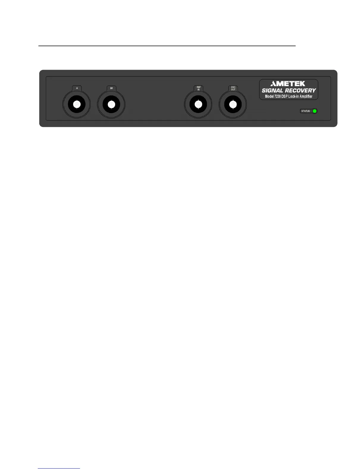
Figure 4-1, Model 7230 Front Panel Layout
As shown in figure 4-1, the model 7230's front panel has four BNC connectors and
an LED Status indicator. The following sections describe the function and location
of these items.
4.1.01 A and B (I) Signal Input Connectors
The A connector is the signal input connector for use in single-ended and differential
voltage mode. The B (I) connector is the signal input connector for use in differential
voltage mode (A-B) and for inverting single-ended voltage mode (-B mode). It is
also the signal input connector when the current input mode is selected.
4.1.02 REF IN Connector
This is the general-purpose input connector for the external reference signal. It will
accept either analog waveforms (e.g. sinusoidal or pulse), or TTL logic signals,
depending on the setting of the reference input control.
NOTE: If the best possible phase accuracy at low external reference frequencies is
required, then a TTL reference signal should be used.
When using dual external reference modes, one of the external references is applied
to this connector and the other to the rear-panel TRIG IN connector (see section
4.2.09).
4.1.03 OSC OUT Connector
This is the output connector for the internal oscillator.
4.1.04 STATUS Indicator
This bicolor LED indicates various operating conditions within the instrument, as
follows:
Instrument Turned Off
The Status indicator is unlit
Instrument Turned On and Operating Normally
The Status indicator is permanently green
Instrument Turned On and Displaying Ethernet IP Address
When the model 7230 is turned on and has determined a valid IP address, either from
a DHCP server, or the Auto IP address function, or is using a static address, then the
Status indicator flashes as it “counts out” the actual IP address. If these flashes are
counted then it is possible to determine the address, as follows.