Chapter 5, WEB CONTROL PANEL OPERATION
5-26
Dual
When selected both sets of demodulators are active, and can be used in the following
ways:
Dual Reference
In dual reference mode the model 7230 can make simultaneous measurements at
two different reference frequencies. These can be internal or external, subject to
the limitation that if two external references are used, one of them cannot be
greater than 3.0 kHz. The Reference controls under Reference 1 and Reference 2
are used to select the source of reference for each demodulator, and for this
mode will be set to different sources.
Dual Channel Detection
Normally the signal input in dual reference mode is common to both
demodulators, and uses the main signal channel. However, it is possible to use
the auxiliary ADC 1 input as the signal input to the second set of demodulators,
allowing the instrument to function as two independent lock-in amplifiers, Note,
however, that in this mode there is no adjustable AC Gain in the ADC 1 input
channel so the range of full-scale sensitivity settings for the second set of
demodulators is limited.
Dual Harmonic
Dual harmonic mode allows the simultaneous measurement of two different
harmonics of the input signal. The Reference controls under Reference 1 and
Reference 2 are used to select the source of reference for each demodulator, and
for this mode will be set to the same source, with each Harmonic control set to a
different value.
Tandem Demodulation
This is essentially the same as dual reference mode but with the input to the
second set of demodulators taken not from the main signal channel or ADC 1
input but from the X-channel output from the first set of demodulators. It allows
the instrument to detect the amplitude of a low frequency modulation of a
higher-frequency carrier signal.
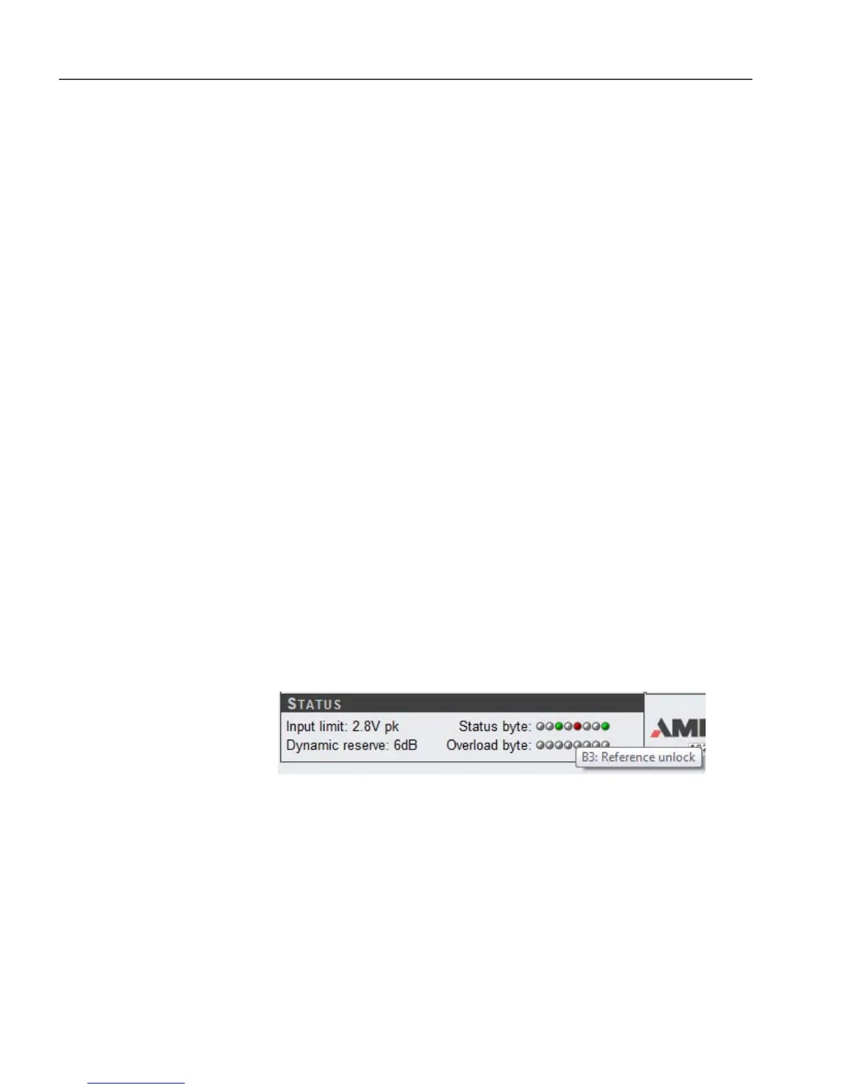
5.3.11 Main Controls: Status Indicators
Figure 5-29, Status Indicators
The Status section gives a quick overview of the instrument status.
Input limit
This is the zero to peak value above which the instrument will be in input overload,
based on the present AC gain setting.
Dynamic reserve
This is the calculated level of Dynamic Reserve based on the present sensitivity and
AC gain settings.
Status byte and Overload byte
These two arrays of LED’s show the bit values in these two bytes, which are defined