Cable Diagrams
Appendix C
C-1
C.1 RS232 Cable Diagrams
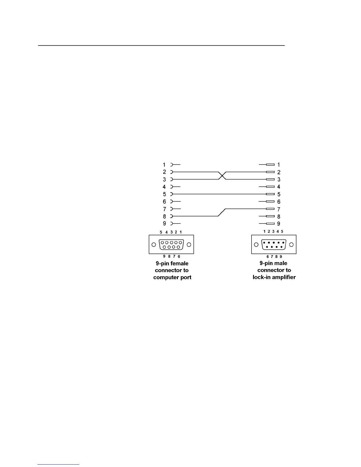
Users who choose to use the RS232 interface to connect the model 7230 lock-in
amplifier to a standard serial port on a computer will need to use one of two types of
cable. The only difference between them is the number of pins used on the connector
which goes to the computer. One has 9 pins and the other 25; both are null-modem
(also called modem eliminator) cables in that some of the pins are cross-connected.
Users with reasonable practical skills can easily assemble the required cables from
parts which are widely available through computer stores and electronics
components suppliers. The required interconnections are given in figures D-1 and
D-2.
Figure C-1, Interconnecting RS232 Cable Wiring Diagram
 Loading...