Chapter 5, WEB CONTROL PANEL OPERATION
5-39
apply otherwise.
5.3.22 Rear Panel: Bind
Figure 5-38, Bind Control
When the bind control, shown in figure 5-38, is checked, it is only possible to
operate the instrument using the web pages from the computer at which this box was
checked. This prevents another user on the same network trying to control the same
instrument.
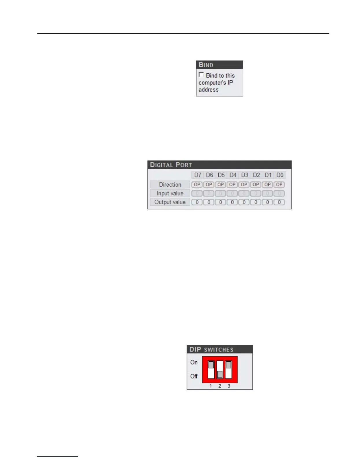
5.3.23 Rear Panel: Digital Port
Figure 5-39, Digital Port
The Digital Port controls and indicators, shown above in figure 5-39, allow the
operating mode of each of the eight pins of the DIGITAL I/O connector on the rear
panel of the instrument to be set and its logic status to be set and read. This port may
be used for controlling or reading the status of external equipment, for example the
switching of heaters or attenuators, via a suitable user-supplied external interface
circuit.
Each of the eight pins is configured as an input or output by the Direction buttons;
when the digit is set to OP it is an output; when set to IP it is an input.
For those bits configured as outputs, the Output value buttons define whether they
are high (value = 1) or low (value = 0); simply click the buttons to change the value.
The Input value indicators show the current logic state of all eight bits, regardless
of whether they are inputs or outputs.
5.3.24 Rear Panel: DIP switches
Figure 5-40, DIP Switches
The DIP switch indicator, shown above in figure 5-40, displays the current position
 Loading...