Chapter 3, TECHNICAL DESCRIPTION
3-3
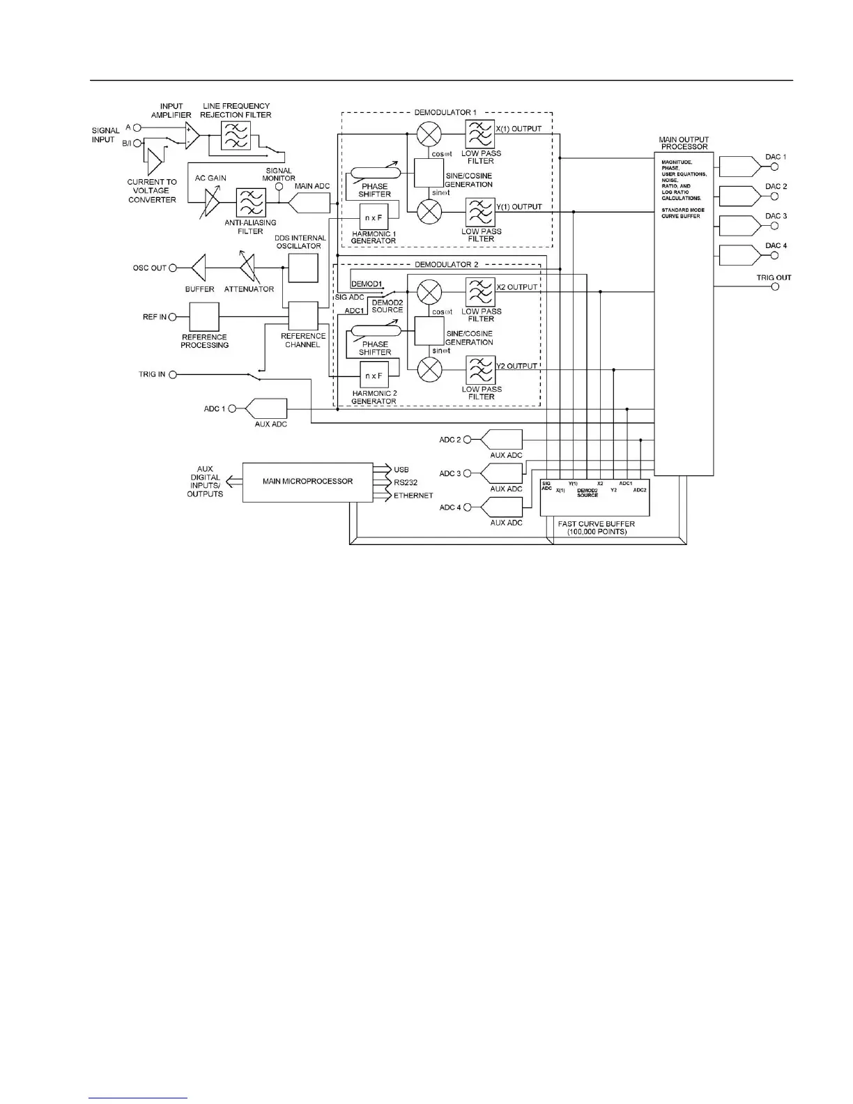
Figure 3-1, Model 7230 - Block Diagram
3.3.02 Signal Channel Inputs
The signal input amplifier can be set for either single-ended or differential voltage
mode operation, or single-ended current mode operation. In voltage mode a choice of
AC or DC coupling is available using an FET or bipolar input device. In current
mode a choice of two conversion gains is available to give optimum matching to the
applied signal. In both modes the input connector shells may be either floated via a
1 k resistor or grounded to the instrument's chassis ground. These various features
are discussed in the following paragraphs.
Input Connector Selection, A / -B / A - B
When set to the A mode, the lock-in amplifier measures the voltage between the
center and the shell of the A input BNC connector, whereas when set to the A-B
mode it measures the difference in voltage between the center pins of the A and B (I)
input BNC connectors.
The latter, differential, mode is often used to eliminate ground loops, although it is
worth noting that at very low signal levels it may be possible to make a substantial
reduction in unwanted offsets by using this mode with a short-circuit terminator on
the B (I) connector, rather than by simply using the A input mode.
The specification defined as the Common Mode Rejection Ratio, C.M.R.R.,
describes how well the instrument rejects common mode signals applied to the A and
 Loading...