Chapter 5, WEB CONTROL PANEL OPERATION
5-27
in the following table:
Bit Status Byte Overload Byte
bit 0 command complete X(1) output overload
bit 1 invalid command Y(1) output overload
bit 2 command parameter error X(2) output overload
bit 3 reference unlock Y(2) output overload
bit 4 output overload CH1 output overload
bit 5 new ADC values available CH2 output overload
after trigger
bit 6 input overload CH3 output overload
bit 7 data available CH4 output overload
Table 5-1, Status and Overload Byte Bit Definitions
The LEDs are green when the corresponding bit is asserted and when this is a “no
fault” condition, and red when it is asserted but this indicates a fault. Bit 0 in each
case is on the right and bit 7 on the left.
If the mouse cursor is hovered over a bit then the bit function is indicated in a pop up
box. In Figure 5-29, for example, the cursor has been hovered over bit 3 in the Status
byte; the fact that this is red indicates a loss of reference lock, while bit 1 indicates
“command done” and bit 5 that the auxiliary ADC inputs have been triggered.
This completes the description of the Main Controls panel.
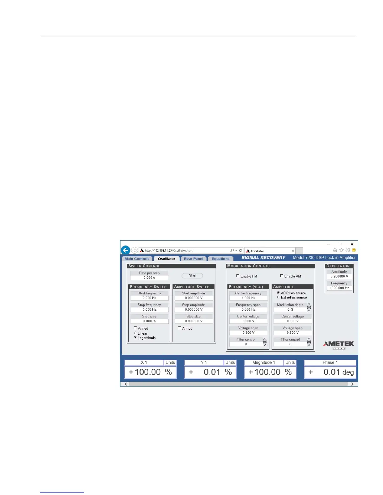
5.3.12 Oscillator: Overview
Figure 5-30, Oscillator Panel
The Oscillator panel, shown above in Figure 5-30, gives access to the full set of
controls for the internal oscillator. Note, however, that the basic controls setting its
amplitude and frequency are also displayed on the Main Controls panel.
 Loading...