24 User Guide EN Dansensor® MAP Mix Provectus
P/N 300862-K
11/2019
Relay signalling
The following describes how relays act during power OFF, normal and fault states:
I/O signals for machine control
I/O machine control:
Start/Stop input
Fault relay
Alarm relay
FAULT Relay State of device
Device OFF DSUB pin 11 connected to pin 12 “Fault” (Off)
Device ON - OK DSUB pin 11 connected to pin 13 “OK”
Device ON - Fault DSUB pin 11 connected to pin 12 “Fault”
DSUB pins/colour Pin 11 - Grey/Pink (Common)
Pin 12 - Blue/Red
Pin 13 - White/Green
ALARM Relay State of device
Device OFF DSUB pin 5 connected to pin 6 “Alarm” (Off)
Device ON - OK DSUB pin 5 connected to pin 7 “OK”
Device ON - Fault DSUB pin 5 connected to pin 6 “Alarm”
DSUB pins/colour Pin 5 - Grey (Common)
Pin 6 - Pink
Pin 7 - Blue
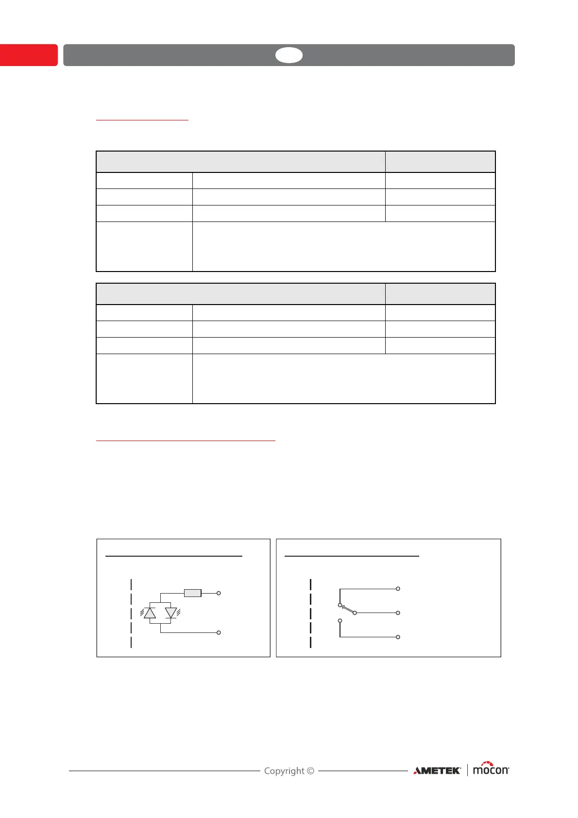
Simplified schematic of control inputs Simplified schematic of relay outputs
Isolation barrier Isolation barrier
Bipolar input
10-32 VDC
Bipolar input
10-32 VDC
Relay output
48 VDC
1A max.
Relay output
48 VDC
1A max.
Normally
Closed (NC)
Normally
Closed (NC)
Common
Normally
Open (NO)
Normally
Open (NO)
+/-
-/+