programmed to control four output relays. Relay MCR for the main contactor and Relay CBR for the
circuit breaker. Relay RL3 can be turned off or configured to follow the Fan Interlock Drive output of the
IPD Relay. Relay RL4, when closed, applies 110V to the CCMD Cable Connecting Module for the
Insulation Test. All of the tripping logic and outlet control is performed by the microprocessor, so that
virtually no external control is required (See Typical Connection Diagram IPDE001, in Appendix A –
Drawings).
The IPD Relay can provide machine communication through the use of a Remote Termination Unit
(RTU-D) connected between the pilot and earth at the machine end of the trailing cable. The IPD’s
protection parameters are automatically uploaded from the remote machine’s RTU-D when the cable is
inserted into a power outlet. For detailed information on the operation of the machine communication
function, refer to Section 8.
Extensive information display and monitoring features are included to facilitate fault finding and system
trending. This information can be read locally on the Remote Display Module (RDM-D) or remotely via a
communication link.
Opto Isolated Outputs are available for connection to optional LED or Relay Modules to provide
additional “run and trip” indications. The Ampcontrol Relay Output Module (ROU) enables these
indications to be interfaced with a PLC. Direct connections to the Opto Isolated Outputs can also be
made for remote monitoring with no additional interfacing required. The maximum voltage for these
outputs is 30V with an internal impedance of 4.7kΩ.
Protection trips are stored in a non-volatile memory requiring a reset function before power can be
restored to the load. This remains the case even if a power down occurs following a trip condition.
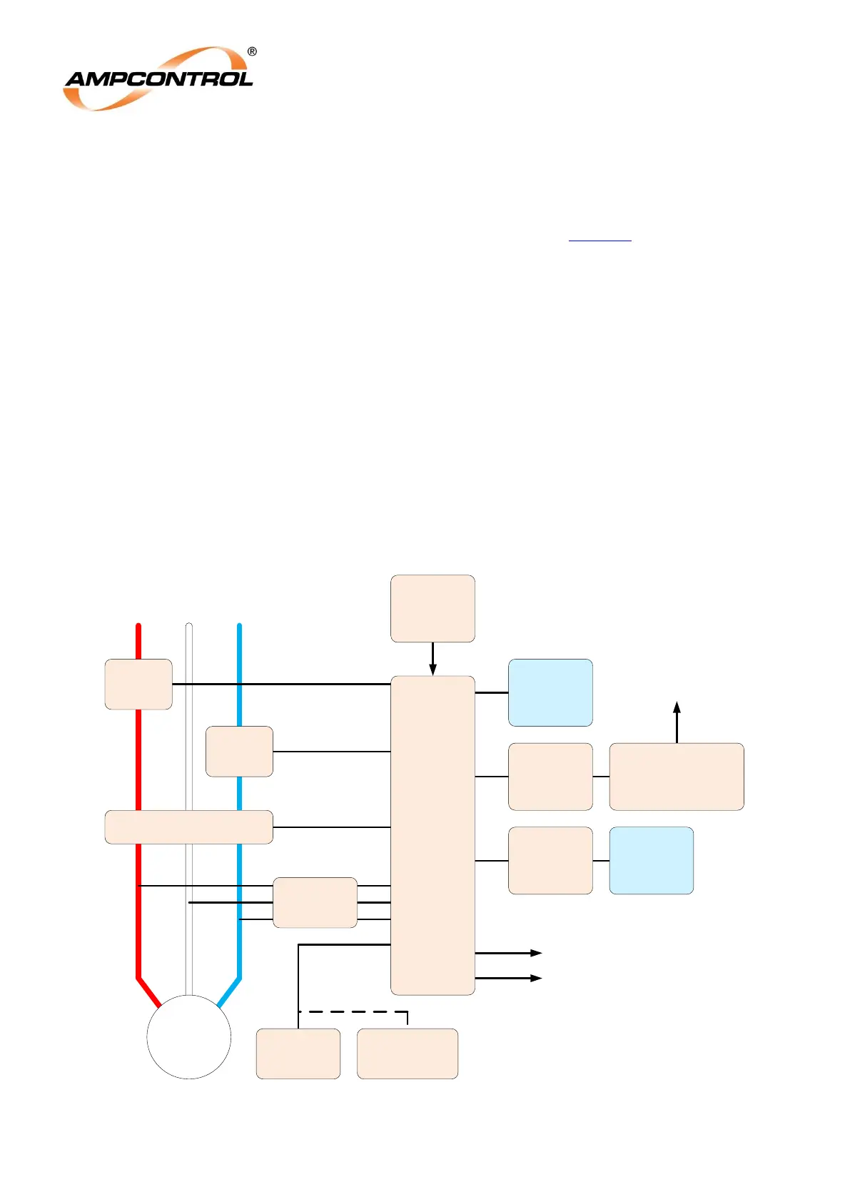
Figure 4.2: IPD System Block Diagram