Ampcontrol Pty Ltd – ABN 28 000 915 542
IPD USER MANUAL
IPDB014 Version 14 – SEP/2020
Uncontrolled Copy - Refer to Ampcontrol Website for Latest Version
APPROVED FOR EXTERNAL DISTRIBUTION
– PROPERTY OF AMPCONTROL PTY LTD
– NOT TO BE REPRODUCED IN PART
9.2.3 Automatic Insulation Test
If a CCMD Mode has been selected in the Group 1 Settings, an automatic High Voltage DC ‘Insulation
Test’ is carried out following a successful Intrinsically Safe Earth Fault Lockout Test (i.e. the resistance
is above the preset level selected in the Group 2 Settings Level 9, Position 15).
The HV DC ‘Insulation Test’ is initiated when the IPD Relay closes its relay output RL4 for 2 seconds.
This applies 110VAC to the CCMD Cable Connecting Module. A HV DC voltage is generated in the
CCMD Module, which applies a voltage approaching the peak system voltage between each phase
and earth.
The IPD Relay measures the voltage on the line and calculates the meg-ohm resistance to earth for
each phase. At the end of the test the result is stored in the Event Log as ‘it -- . - MΩ’. If the resistance
value is above the preset threshold the MCR Relay picks up allowing the outlet to be energised.
Additionally, if the result is equal to or below an Alarm Level (typically 1.5 times the selected trip level,
see Table 6) the status message ‘Insulation Alarm’ is displayed on the Status Page (level 0, position
0). The alarm message is displayed until a new EFLO Test is initiated or the <ENT> key is pressed
while displaying the alarm message. ‘Insul. Alm’ is also recorded in the Event Log.
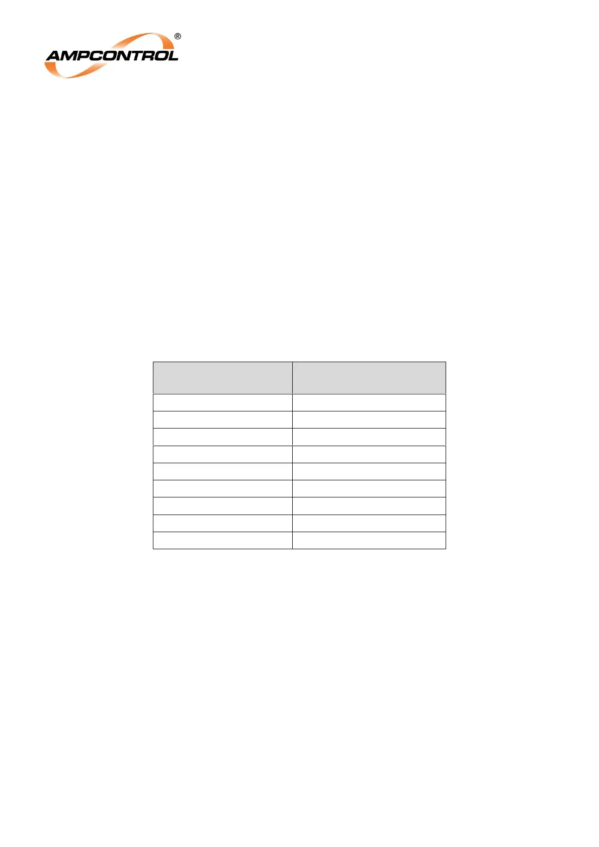
Table 6: Insulation Test Trip Threshold and Alarm Level Comparison
If the value is less than the preset trip level (0.1 MΩ to 15 MΩ) a trip occurs and is latched and saved in
a non-volatile memory. The “EF” LED on the Remote Display Module is illuminated and the open
collector output on the relay is switched on to provide remote monitoring if required. An Insulation Trip
shares the “EF” LED on the Remote Display Module with an EFLO trip but has dedicated trip
messages on the Status Page. To reset the relay following an insulation test fail trip, operate the reset
button.
At the completion of a test the leakage level for each phase is retained in memory until the next test is
carried out. This can be viewed on the Remote Display Module RDM (Level 3, Position 3).
If the ‘Insulation Test’ is not selected by either not selecting CCMD or setting ‘Ins.TstT:’ value to ‘None’
then the MCR Relay closes at the completion of a healthy EFLO Test.
The accuracy of the insulation test and expected trip ranges are outlined in Table 7. The results from
insulation test should only be used as a guide to confirm that insulation remains above the preset
threshold. Insulation tests apart from the generated insulation test via the IPD and CCMD should be
still carried out on a regular basis for maintenance purposes.