Ampcontrol Pty Ltd – ABN 28 000 915 542
IPD USER MANUAL
IPDB014 Version 14 – SEP/2020
Uncontrolled Copy - Refer to Ampcontrol Website for Latest Version
APPROVED FOR EXTERNAL DISTRIBUTION
– PROPERTY OF AMPCONTROL PTY LTD
– NOT TO BE REPRODUCED IN PART
5.4.3 Low Voltage Signals
Although these signals are not IS signals themselves, care must be taken to ensure these circuits
cannot come into contact with higher voltages (e.g. via insulation breakdown, or broken wires etc.). It is
recommended that these circuits be run in a separate loom from both the IS circuits and the “high”
voltage circuits. To ensure that interference is kept to a minimum, the following cabling is required.
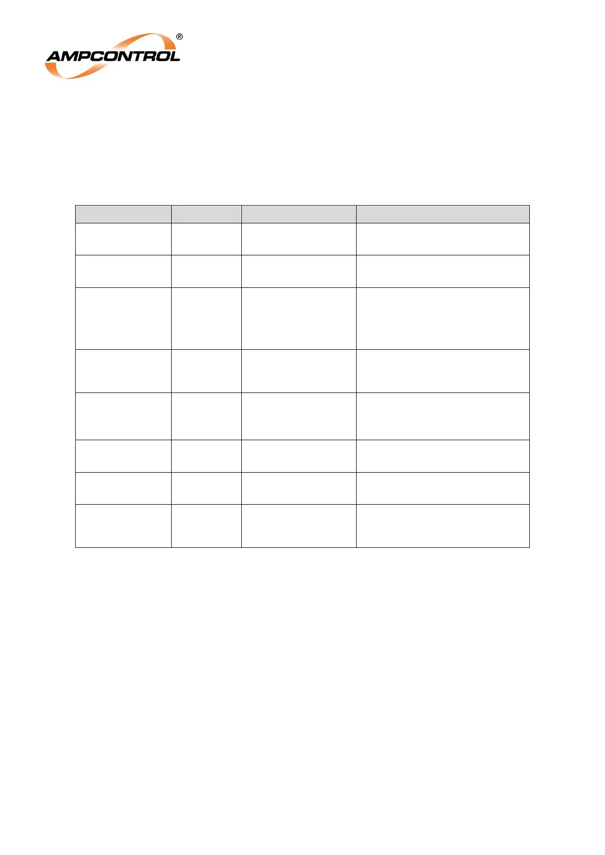
Table 2: Cable Requirements: Low Voltage Signal Circuits
Two core screened
Screen = Earth
Earth Leakage
Toroid Test
Single core, not screened. Loop
Resistance < 1
Current
Protection
Transformers
2xTwo core screened
Screen = Earth
Local Stop
Button
(Digital Input)
*Two core screened
Screen = Earth
Lock Switch
(Digital Input)
*Two core screened
Screen = Earth
Reset Switch
(Digital Input)
*Two core screened
Screen = Earth
Start Switch
(Digital Input)
*Two core screened
Screen = Earth
Motor Contactor
Aux Contact
(Digital Input)
*Two core screened
Screen = Earth
* The IPD’s digital inputs could alternatively be run in a screened multi-core cable. (Separate cable for
each IPD Relay in multiple installations.)
Where these “low voltage” circuits need to connect near the power circuits (e.g. current transformers,
cable connection module, main contactor auxiliaries etc.), care needs to be taken to ensure that the
circuits are adequately separated and restrained so that the separation is maintained, even if a wire
termination comes loose etc.