APPROVED FOR EXTERNAL DISTRIBUTION
– PROPERTY OF AMPCONTROL PTY LTD
– NOT TO BE REPRODUCED IN PART
16 REMOTE DATA COMMUNICATIONS
The IPD Integrated Protection Relay has the facility for connecting remote monitoring equipment. This
can be in the form of either the Remote Display Module or other peripheral equipment such as PLC’s.
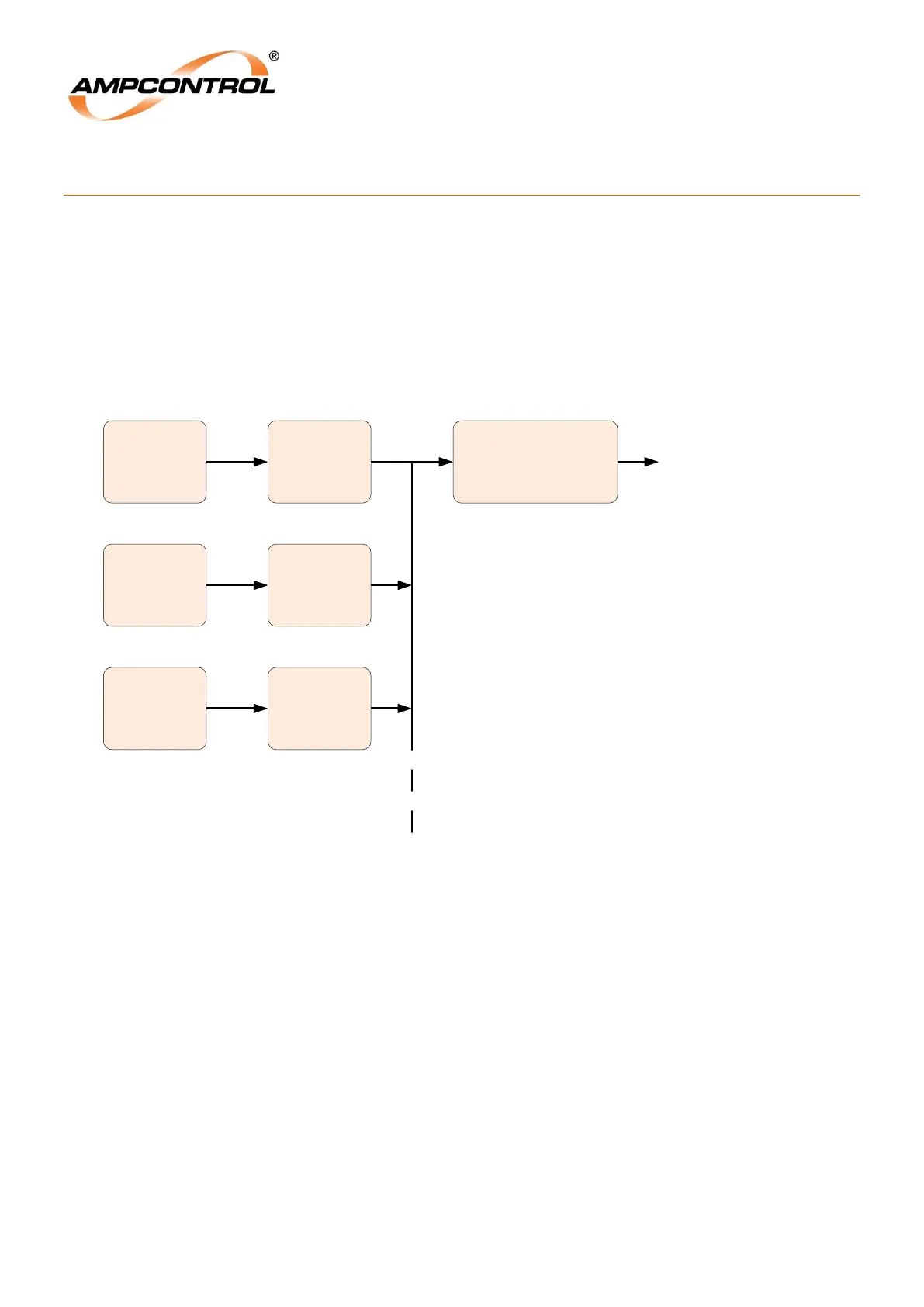
For PLC applications each integrated protection relay is connected to a Serial Interface Module (IPSI-D),
which has its output drop connected to a DNET-IP2 Protocol Converter. The Protocol Converter provides
the communications link to a PLC (see DNET-IP2 Serial Communication System User Manual for further
details).
The Ampcontrol DNET-IP2 Serial Communication System transfers data and commands between the
Host System and the modules using RS232, RS422 and RS485 protocols.
Figure 16.1: PLC Communications Block Diagram