APPROVED FOR EXTERNAL DISTRIBUTION
– PROPERTY OF AMPCONTROL PTY LTD
– NOT TO BE REPRODUCED IN PART
13 USER ADJUSTABLE SETTINGS
13.1 Parameter Groups
There are two groups of adjustable settings contained in the IPD Relay’s non-volatile memory. Both
groups can be viewed and modified via the Remote Display Module.
The first group of settings is always stored in the relay and relates to parameters which are linked to the
system rather than the particular load connected to the outlet.
The second group of settings consists of parameters that are related to the load connected to the
protected outlet. These settings are stored and retrieved to/from the memory in the IPD Relay or the
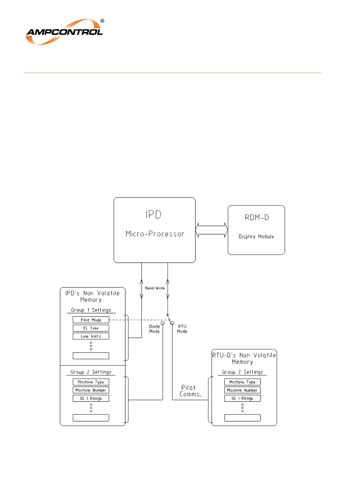
memory in the Remote Termination Unit, depending on the “Pilot Mode” setting. Figure 13.1 shows how
the memory is “switched”.
If diode pilot mode is selected, the IPD Relay reads and writes to and from the relay’s internal memory
for the Group 2 settings.
If RTU Mode is selected, the Group 2 settings are sent to and retrieved from the memory in the Remote
Termination Unit.
Figure 13.1: Memory “Switching” for Group 2 Parameters