APPROVED FOR EXTERNAL DISTRIBUTION
– PROPERTY OF AMPCONTROL PTY LTD
– NOT TO BE REPRODUCED IN PART
9.1.4 CT Detection Monitoring
The IPD generates a CT Detection Signal continuously to test the integrity of earth leakage circuit. The
CT Detection signal continually tests the toroidal current transformer, the wiring loop to the toroid and
the input to the protection relay as required by AS/NZS 2081.3 - 2002.
The signal generated by pins 32 and 33 is a 20mA signal at 200Hz. It must be fed from pin 32, one
loop through the toroid then back to pin 33.The CT detection signal can be monitored by pushing the
‘Enter’ switch when viewing the ‘Earth Fault Information’ on Level 3 position 1 of the Remote Display
Module.
When the trip occurs the remote display module “EL” LED will flash and the open collector output on
the relay is switched on to provide remote monitoring if required.
The trip time for a CT detection fault has been fixed at 4 seconds in Version 5 of the IPD relay. This
differs from earlier versions of the IPD firmware that derived the trip time from the Earth Leakage Time
Delay setting.
The loop resistance of the CT Detection Signal circuit connected to
pins 32 and 33 must remain below 1Ω.
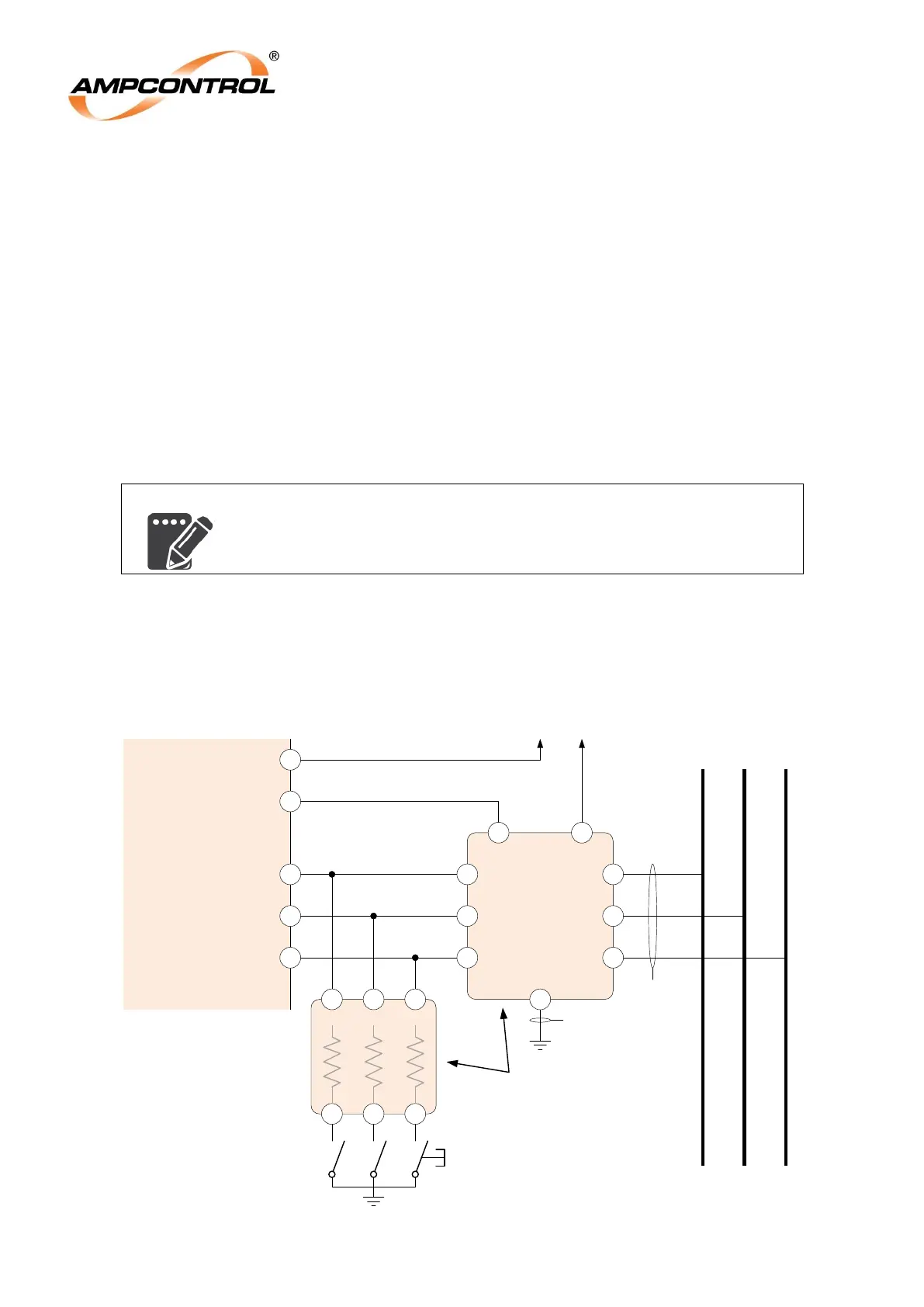
9.2 Earth Fault Lockout Protection
The IPD relay can provide a two-step insulation test as part of the Earth Fault Lockout protection
function. The initial test is the mandatory intrinsically safe test and can be followed by an automatic High
Voltage ‘Insulation Test’. A manual ‘Insulation Test’ is also provided.
Figure 9.2: Earth Fault Lockout Protection Circuit Terminations