Ampcontrol Pty Ltd – ABN 28 000 915 542
IPD USER MANUAL
IPDB014 Version 14 – SEP/2020
Uncontrolled Copy - Refer to Ampcontrol Website for Latest Version
APPROVED FOR EXTERNAL DISTRIBUTION
– PROPERTY OF AMPCONTROL PTY LTD
– NOT TO BE REPRODUCED IN PART
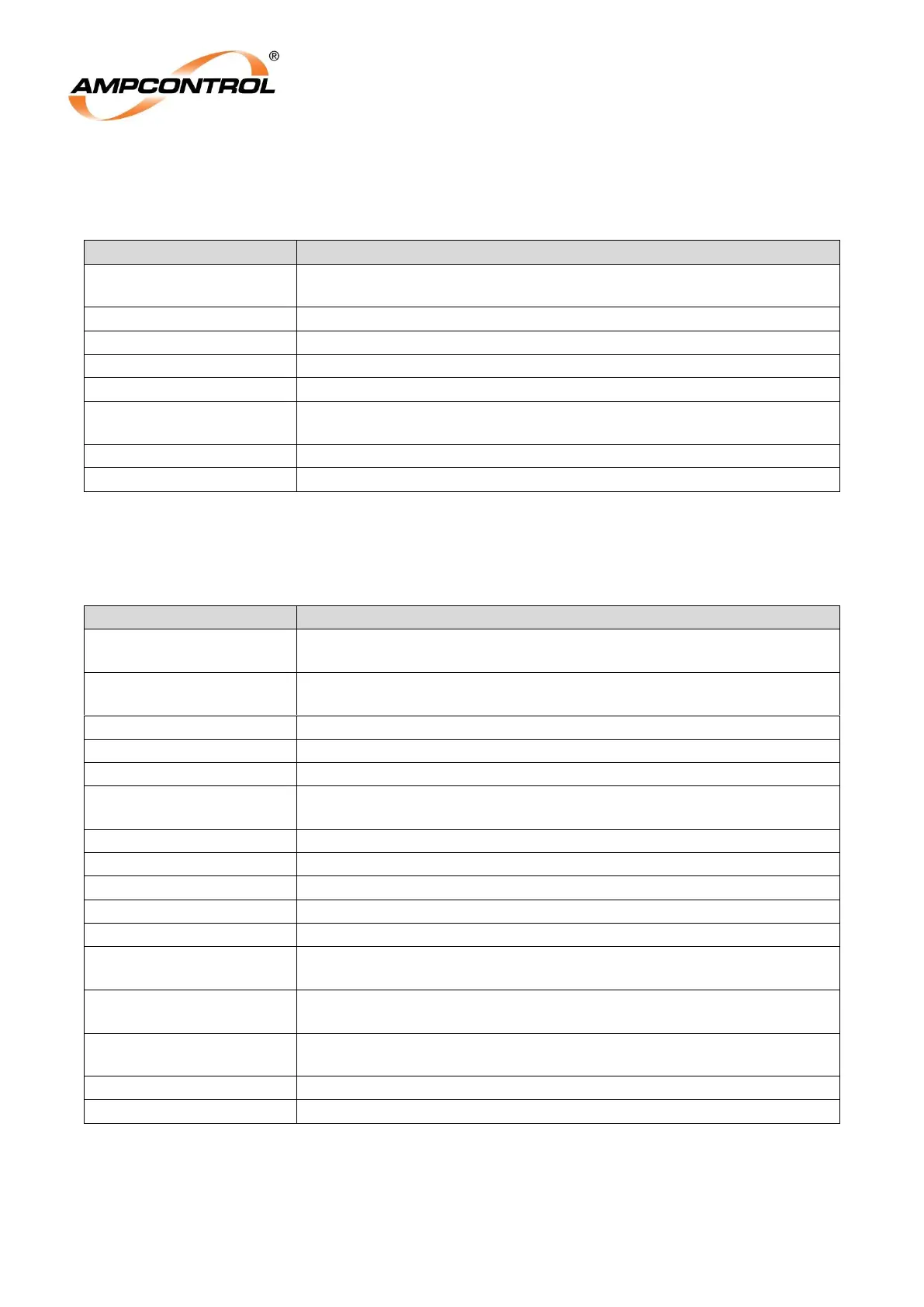
13.1.1 Group 1 Settings (Stored in the IPD)
Table 8: Group 1 Settings
Determines if the pilot is to be terminated with a diode or remote
termination unit
Sets the trip time for the earth leakage protection
Sets the sensitivity trip level for the earth leakage protection
Selects the Cable Connection module to be used with the IPD Relay
Selects the under-voltage trip threshold as a % of line volts
Selects which output relay (MCR or CBR) is tripped in event of a
short circuit trip
Sets the trip time for the earth continuity protection
Selects “off”, “FID” or “FIR” operation of the relay
13.1.2 Group 2 Settings (Stored in the RTU-D)
Table 9: Group 2 Settings
Selects the RTU descriptive code transmitted to identify the machine
connected to the outlet.
Selects the assigned machine number to be transmitted by the
Remote termination Unit.
Sets the basic current range
This multiplier combines with OC range to define the full load current
Selects either very inverse over-current or motor overload protection
Modifies the basic over-current time curves to achieve the desired trip
times
Allows the cooling rate of the thermal model to be modified
Adjusts current phase balance trip
Sets the short circuit trip level
Sets the trip time for the short circuit function
Determines whether earth continuity trips are self-resetting or not
Adjustable time delay to inhibit main contactor fail following opening
of main contactor
Sets the fan current threshold at which other outlets are allowed to
run
When “Yes” is selected the IPD Relay ignores the local start input.
When “No” is selected the local start/stop inputs control the relay
Sets the trip threshold or disables the function
Adjusts the parameters of the transient overreach function of the IPD