APPROVED FOR EXTERNAL DISTRIBUTION
– PROPERTY OF AMPCONTROL PTY LTD
– NOT TO BE REPRODUCED IN PART
When installing the IPD Relay care should be taken to ensure sufficient space is allowed around the
relay for the ease of change out during routine maintenance.
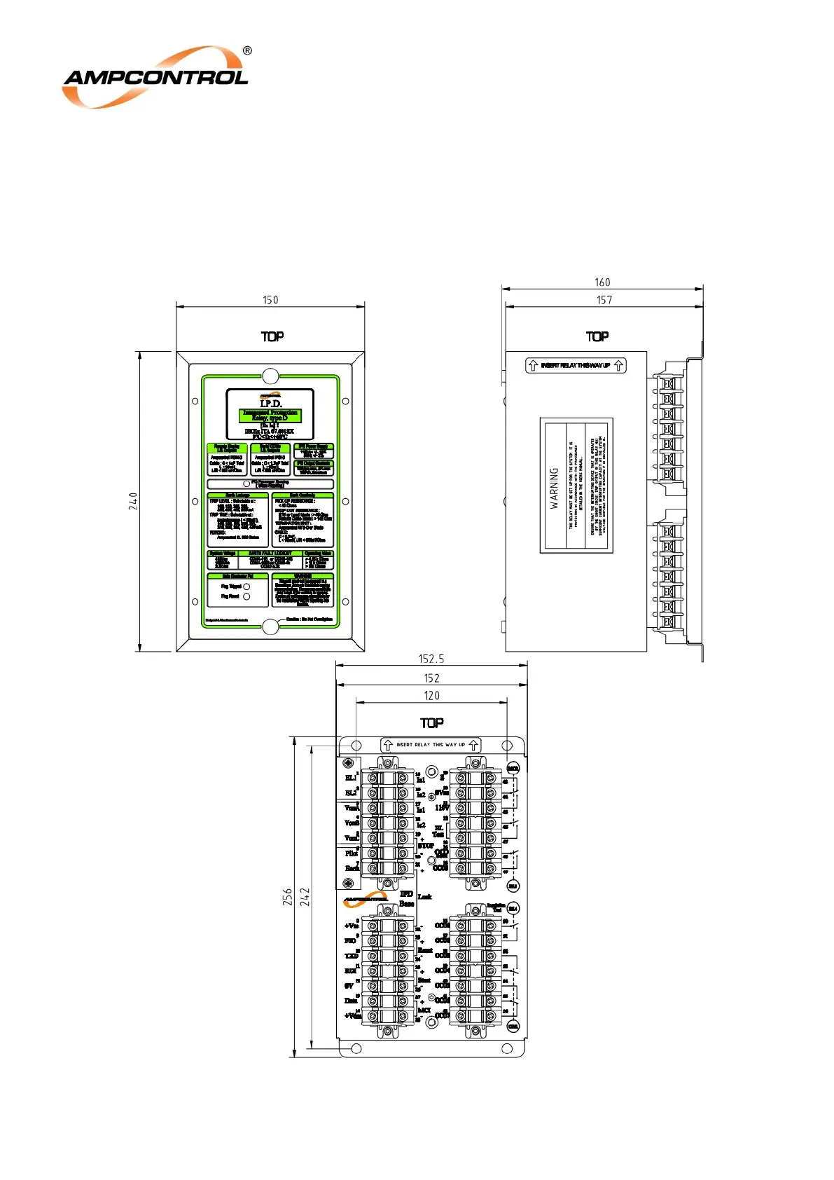
Connections to the IPD Relay are made via a plug in base. This base is to be securely fastened to the
enclosure in which it is being installed. The base is clearly labelled for ease of terminal location and
identification. The base sockets are factory adjusted so that they are able to move to assist in
alignment when the relay is inserted. Do not tighten socket mounting screws.
Figure 5.2: IPD Relay and Base Dimensional Details